EICU – Engine Interface Control Unit
The EICU (Engine Interface Control Unit) is responsible for connecting the Engine Control System with external systems. There are two EICU units installed: EICU A and EICU B. If one unit fails, the other provides redundancy to ensure continued operation. The EICU interfaces with the Engine Remote Control System, telegraph, and Engine Safety System, and manages engine RPM commands, speed settings, and engine load programs.
The speed commands provided by the operator are received by the EICU. The EICU processes these speed set points using algorithms designed to ensure smooth operation without adversely affecting the engine. For example, it handles barred speed protection and load-up programs. The processed speed set point is then sent to the ECU, which adjusts the engine to achieve the desired RPM set point.

ECU – Engine Control Unit
The ECU (Engine Control Unit) also comes in two units, similar to the EICU, providing both main and redundancy functions. Its primary responsibility is to operate the governor. It calculates the fuel index based on the processed speed set point provided by the EICU. Additionally, the ECU determines fuel injection timing, exhaust valve timing, and cylinder lubrication rate for modes such as NOx and ECO, and communicates this information to the CCU. The ECU also controls the opening and closing of the pilot valve for the Main Starting Air Valve.
Typically, with three engine-driven hydraulic pumps, the ACU (Auxiliary Control Unit) MPC manages them. However, in some large engines with five engine-driven hydraulic pumps, the ECU units take responsibility for pumps number 4 and 5. In such cases, while the ECU still consists of two units, it does not provide redundancy.
CCU – Cylinder Control Unit
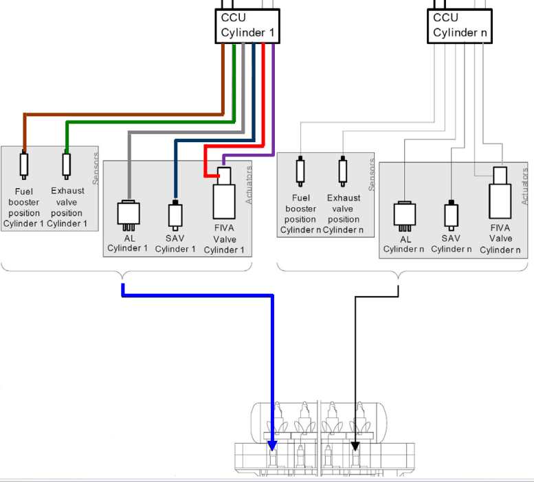
The Cylinder Control Unit (CCU) is responsible for controlling one cylinder unit per card, and it does not have redundancy. As mentioned earlier, the MPC-10 is sometimes used instead of the MPC for the CCU. In such cases, the vessel should have both a new MPC card and a new MPC-10 card on board.
The CCU controls the Hydraulic Control Unit (HCU) of each cylinder unit. The HCU is a hydraulic control assembly responsible for fuel injection, exhaust valve actuation, and cylinder lubrication for each cylinder. Further details will be explained later.
The CCU retrieves the crank angle position from the Tacho System and uses this information to manage fuel injection and exhaust valve actuation for the relevant units.
The ECU sends Injection Profile Commands to the CCU. According to the received commands, the CCU initiates fuel injection when the crank angle reaches the specified position. The Fuel Oil Pressure Booster starts the fuel injection, and the fuel flow is controlled by the hydraulic piston actuator of the Fuel Booster Unit through the ELFI (Electronic Fuel Injection) Proportional Valve.
In ME-C engines, the ECU controls the opening and closing of the exhaust valve at the specified crank angle using the ELVA (Exhaust Valve Actuation) system for On/Off control. There are systems with separate ELFI and ELVA valves, as well as systems where the FIVA (Fuel Injection Valve Actuation) performs both functions. In ME-B engines, only the ELFI is used for fuel injection, while exhaust valve actuation is handled through the cam shaft, similar to MC engines.
ME-C engines do not have a Starting Air Distributor like MC engines. Instead, CCUs control the pilot valves of the Air Starting Valves in each cylinder unit according to the firing order and forward/reverse sequence.

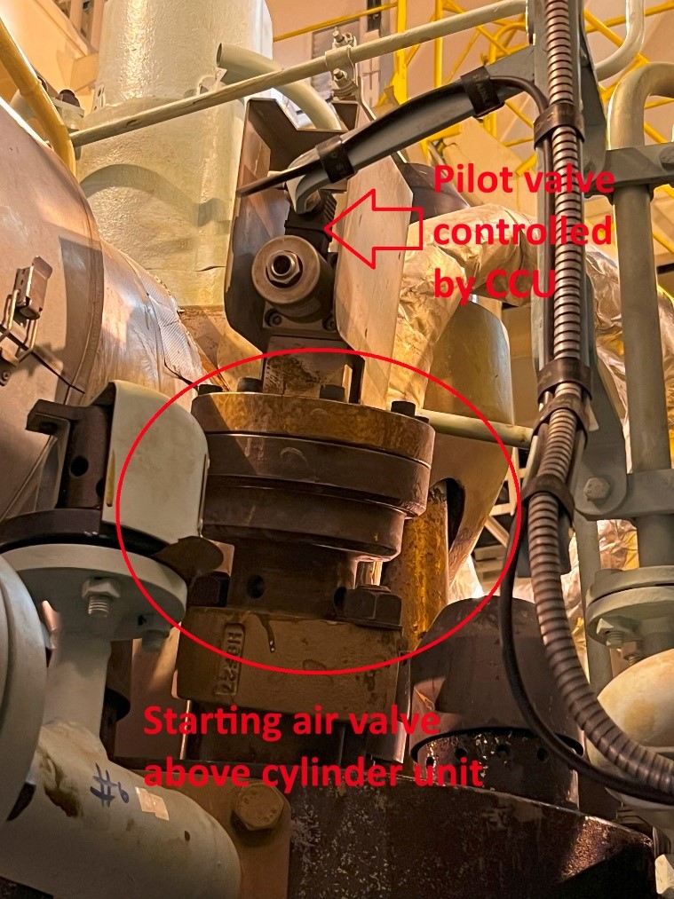
Picture : Starting Air Valve and Pilot Control Valve of ME Engine 9 (c) Kyaw Soe Aung
As previously mentioned, the CCU controls one card per cylinder unit and does not have redundancy. If the card fails, fuel supply and exhaust valve operations will cease, causing the cylinder unit controlled by that card to become out of operation and resulting in engine slowdown.
One critical aspect related to the CCU is cylinder lubrication. The cylinder lubricator solenoid valve is integrated with the HCU (Hydraulic Control Unit). Under normal conditions, the ECU sends the cylinder lubrication rate to the CCU based on factors such as sulfur content in fuel, feed rate factor, and minimum feed rate. The CCU then controls the lubrication by adjusting the on/off frequency of the lubricator solenoid and managing the feed rate.
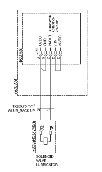
If the CCU card fails or is not immediately replaceable, cylinder lubrication may stop, worsening the situation. In such cases, an emergency lubrication cable is provided. This cable should be connected to plug 52 of ECU A (or ECU B) and the lubricator solenoid. After connecting, the ECU will supply lubrication to the lubricator at random timings. The emergency lubrication cable should be stored in a designated location for easy access during emergency situations and properly documented.

Details of the remaining MPCs will be explained in Section (3).
References
1) Hyundai-Man B&W Diesel Engine Main Engine Manual Volume II
2) MAN Diesel PrimServ Academy
Kyaw Soe Aung (0323 HR 28 JUL 24, Bangkok, Thailand)
(This overview of ME Engine Control Systems is intended solely for educational purposes and knowledge sharing. It is not designed for commercial publication or professional use. The information provided aims to offer a general introduction to ME Engine Control Systems for those unfamiliar with the topic.
Please be aware that this overview is based on specific ME engines encountered and reflects current technology as of the date of writing. Due to the evolving nature of technology, there may be gaps, discrepancies, or inaccuracies in the information presented.
For the most accurate and up-to-date information, further research and consultation with industry experts are recommended. Corrections, additional insights, and feedback from the community are welcome to enhance the accuracy and usefulness of this material.)

Leave a comment