Auxiliary Control Unit (ACU)
There are three ACUs, and they are responsible for managing the Hydraulic Power Supply Pump and the Auxiliary Blower. The ACU operates the start and stop functions of the auxiliary blower based on scavenge air pressure. Additionally, it controls the flow for engine-driven hydraulic pumps and the start/stop functions for electric-driven pumps.
In some engines, where the electric-driven pumps are variable types, the ACU also controls the swag plate position of these pumps. Instead of connecting pumps and blowers to a single ACU card, each card is connected uniformly to ensure that if one ACU card fails, engine operation will not be impacted.
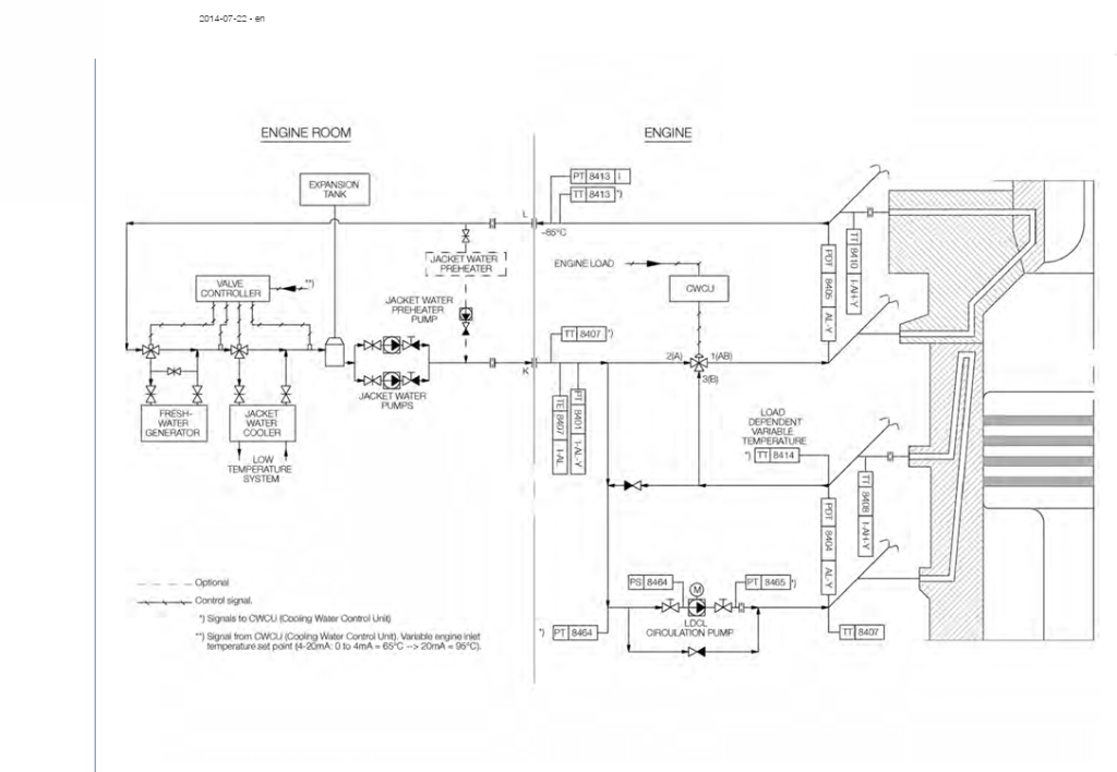
Cooling Water Control Unit (CWCU)
The Cooling Water Control Unit (CWCU) is an essential component in ME engines. It includes two control processes: the Load Dependent Cylinder Liner (LDCL) control system and the Load Dependent High Temperature (LDHT) control system. In the current vessel during writing this paper, only the LDCL control process is implemented.
The LDCL system is designed to mitigate cold corrosion issues in the cylinder liner caused by sulfur in the fuel. It regulates the temperature of the liner cooling water based on engine load and fuel sulfur content. This involves controlling the amount of cooling water recirculated through the liner and the jacket water coming from the jacket cooler using a 3-way mixing valve to maintain the desired temperature of the liner cooling water. A circulation pump is installed to ensure efficient water flow. The LDCL calculates and sets the set points for both the liner cooling water temperature and the jacket cooling water temperature.
The LDHT system functions similarly to the LDCL. However, while LDCL only controls the liner cooling water temperature, LDHT manages the jacket water temperature for the entire engine, adjusting it based on engine load and sulfur content.

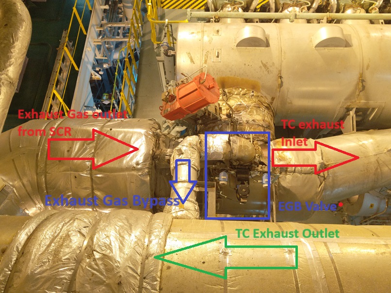
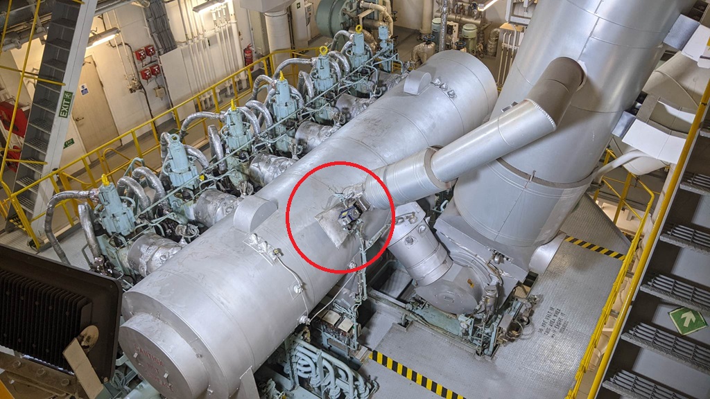
Scavenge Air Control Unit (SCU)
The Scavenge Air Control Unit (SCU) is responsible for regulating scavenge air pressure. It manages the position of the Exhaust Gas Bypass (EGB) valve and controls the Variable Turbocharger (VT) if present.
The EGB valve directs exhaust gas away from the turbocharger and towards the turbocharger exhaust outlet, bypassing the turbocharger. By adjusting the opening and closing of the EGB valve as needed, the SCU regulates the scavenge air pressure.
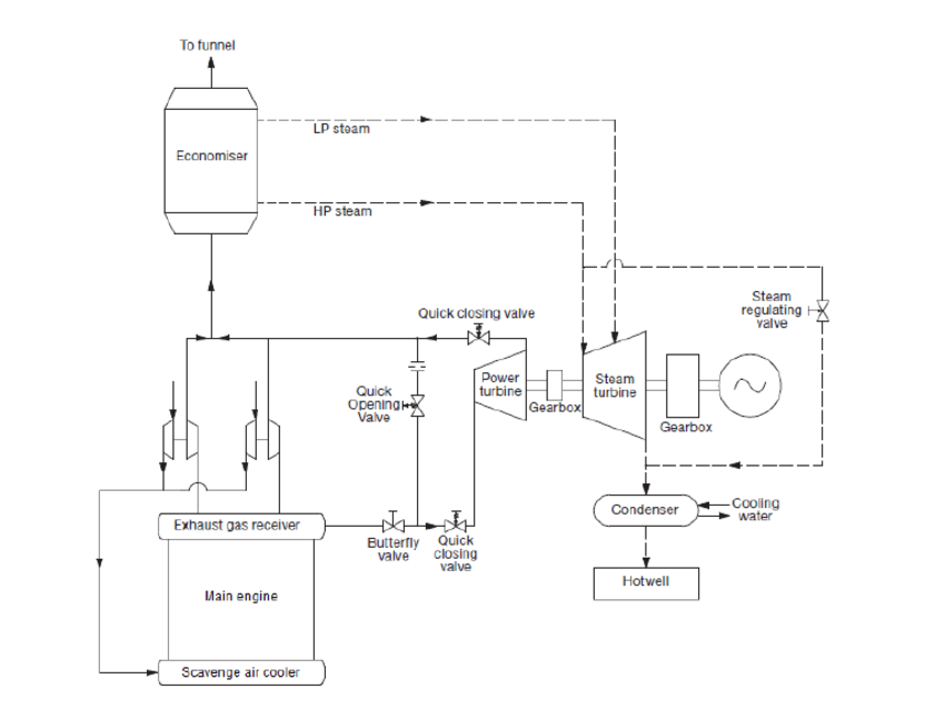
In some engines, the SCU also controls the Various Waste Heat Recovery (WHR) system in addition to the EGB valve. The WHR system is designed to recycle the heat released by the engine to prevent it from being wasted. Simply put, it functions like an economizer.
Engine manufacturers are working hard to reduce fuel consumption and lower emissions. For example, MAN B&W’s WHR system design integrates an economizer with a steam turbine and power turbine that utilizes exhaust gas flow to generate electrical power.
MPCs for SCR and EGR
SCR (Selective Catalytic Reduction) and EGR (Exhaust Gas Recirculation) are two advanced technologies that have been added to the Main Engine Control System to enhance emission reduction. Controllers for these systems are often implemented using MPC (Multi-Purpose Controllers). Additionally, there are separate MOP (Main Operating Panel) for each system.
For the operation and control of the valves associated with SCR and EGR systems, there is typically one Control Unit MPC and one Interface MPC for each system.
Further details on SCR and EGR will be provided later.
EMS – Engine Management Service
The Engine Management Service (EMS) includes the following components:
- PMI Online System
- ACCo
- CoCs-EDS
PMS – Pressure Measurement System
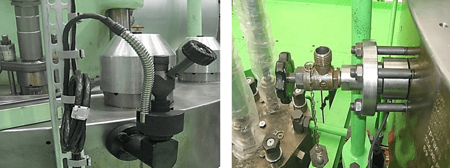
In the Pressure Measurement System (PMS), each cylinder unit is equipped with pressure sensors installed in the indicator cocks to measure pressure throughout the combustion process. The pressure sensors used are from Kistler and ABB.
Kistler Sensors: These are piezoelectric sensors. Piezoelectric sensors generate an electric charge when subjected to pressure, causing a slight deformation in the sensor material. This change in electric charge produces an electrical signal, which is then processed and amplified to determine the pressure value. Kistler pressure sensors typically have a lifespan of about four years. A drawback is that if the indicator cock is opened while the engine is running, the sensor can be damaged due to the effects of high temperatures.
ABB Sensors: These are magnetic elastic type sensors. They measure pressure by detecting changes in the magnetic field caused by the deformation of the sensing material due to cylinder pressure. ABB sensors are generally more expensive than Kistler sensors and have a lifespan of around ten years.
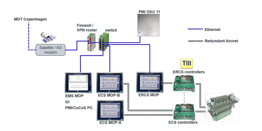
Each cylinder unit’s sensors measure pressure and other parameters. The Data Acquisition Unit (DAU) collects data from these sensors, including the crankshaft angle position and engine RPM sensor readings provided by the Tacho System. The DAU then transmits this data to the PMI computer via a LAN connection.


PMI System
The PMI system is designed to continuously and easily monitor critical parameters of each engine unit, such as p(i), p(comp), and p(max). This allows operators to view these values and constantly monitor engine performance. It also facilitates easier decision-making for adjustments and tuning as needed.
ACCo – Adaptive Cylinder Control
ACCo is an algorithm that analyzes data from the PMI system to continuously tune and adjust engine performance. It calculates parameters such as the fuel injection profile and exhaust valve timing to ensure optimal engine performance. ACCo works in conjunction with MOP B to perform these functions.

CoCoS -EDS (Computer Controlled Surveillance- Engine Diagnostic System)
CoCos က Engine ရဲ့ Performance data တွေကို အသေးစိတ်တွက်ချက်ပြီး operator ကို Engine ပြဿနာတွေ ဖြေရှင်းရာမှာ ကူညီတဲ့ program ဖြစ်ပါတယ်။ cylinder pressure and crank angle,, combustion pressure, exhaust gas temperature, Fuel injection timing, Engine load diagram စတာတွေကို ပြည့်ပြည့်စုံစုံ Graph နဲ့ trend တွေ အဖြစ် real time monitoring လုပ် လို့ရပြီး operator အနေနဲ့ ကိုယ့် engine ကို ကောင်းစွာ ထိန်းချုပ်နိုင်မှာဖြစ်ပါတယ်။
References
1) Hyundai-Man B&W Diesel Engine Main Engine Manual Volume II
2) MAN Diesel PrimServ Academy
Kyaw Soe Aung ( 2230 HR 29 JUL 24, Yangon, Myanmar)
(This overview of ME Engine Control Systems is intended solely for educational purposes and knowledge sharing. It is not designed for commercial publication or professional use. The information provided aims to offer a general introduction to ME Engine Control Systems for those unfamiliar with the topic.
Please be aware that this overview is based on specific ME engines encountered and reflects current technology as of the date of writing. Due to the evolving nature of technology, there may be gaps, discrepancies, or inaccuracies in the information presented.
For the most accurate and up-to-date information, further research and consultation with industry experts are recommended. Corrections, additional insights, and feedback from the community are welcome to enhance the accuracy and usefulness of this material.)

Leave a comment