Replacing the MPC Card
If an alarm goes off on an MPC card, you can read the alarm information from the MOP panel to determine what might be causing the issue. It provides explanations for all possible causes. Some issues and errors can sometimes be resolved by performing a reset.
Resetting redundant cards like the EICU does not typically cause the engine to slow down or stop. However, resetting cards such as the CCU and ACU can lead to engine slowdown. Therefore, it is advisable to perform such resets only when the ship is in a safe area.
If a reset does not resolve the issue and the LED on the MPC card is showing red (indicating a fatal error), you will need to replace the card.
When replacing the card, follow standard procedures and first turn off the power supply. The power supply cabinet for MPC cards is usually located in the Engine Control Room. If there are two power supplies, both must be turned off.
Since you will be handling electronic PCBs, you should ground yourself before replacing the card, either by grounding your body or wearing a wrist strap. Replacing the MPC card itself is not complicated. After turning off the power supplies from the cabinet, disconnect the power supply plug from the card. Then, disconnect the Network A and Network B plugs, followed by removing the ID key. Finally, remove the remaining plugs, making sure to note the plug tags and positions for reference.
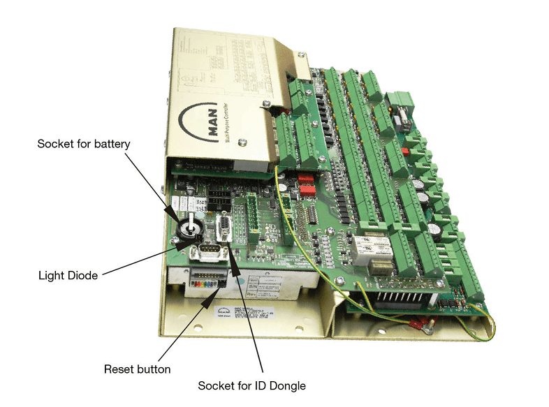
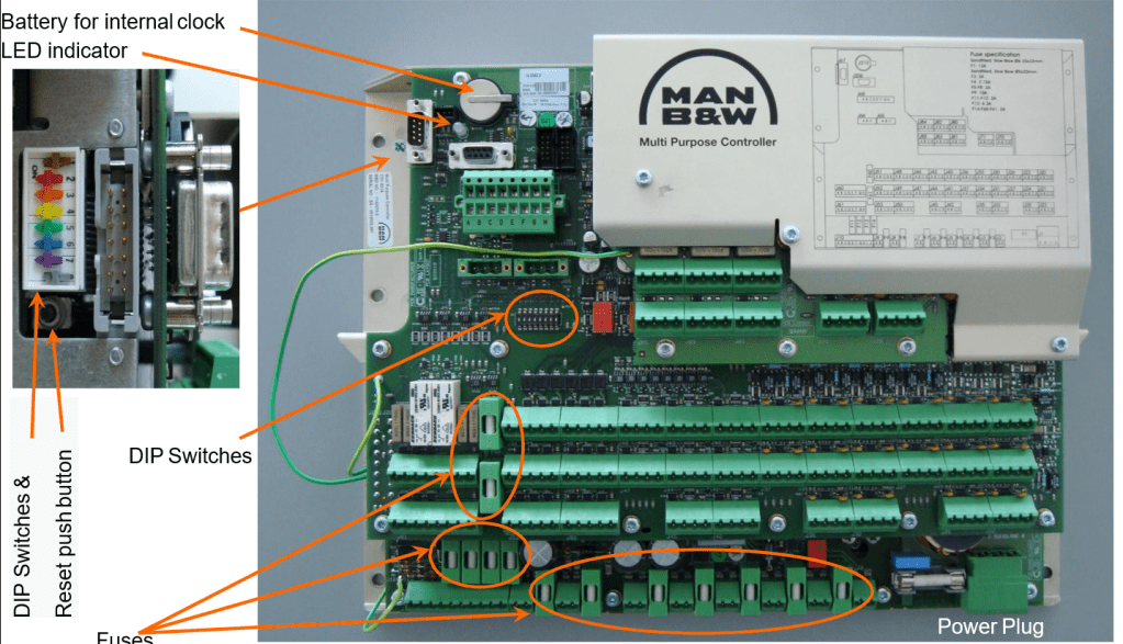
When installing a new card, the first step is to check that the DIP Switch S1 and the Colored DIP switches are correctly set. DIP Switch S1 should be in the OFF position for all switches. For the Colored DIP switches, the switches at the beginning and end (No. 1 and No. 8) should be OFF, while the remaining switches should be ON.
Next, verify whether the backup battery is present. If the battery is missing, the card may restart by itself.
After this, simply reverse the previous steps to complete the installation. Reconnect the plugs, insert the ID key, reconnect the Network plugs, and finally, connect the power cables. The power should be turned on, and the system should be operational.
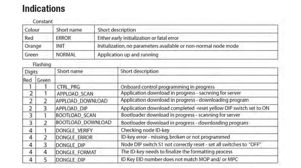
After powering on, the MPC card will obtain its address from the ID key and download the relevant software from the MOP. This process may take about 4 to 5 minutes. The card’s status during downloading and initialization can be monitored through the LED indicators. Once the download and installation are complete, the LED should turn green. You can also check on the MOP panel under System Maintenance to confirm that the card is operational. If the LED does not turn green and a significant amount of time has passed, you may need to reset the card and restart the process.
The location where the new card is stored is also important. Typically, it is kept in the CE room. Ensure that it is stored in a dry, secure place where it cannot be exposed to moisture or physical damage. If the new card was damaged before installation or if there is no spare card available, you may need to use an MPC card from another location. Redundant cards like the EICU can be used, or for a Tier II Engine, an SCU MPC can be used.
If using a previously installed card, the steps for installation are similar to those for a new card. Remove the faulty MPC, install the MPC from another location (e.g., EICU), and when power is turned back on, the MPC will recognize if the address from the ID key differs from its existing address. In such cases, the ID key’s address will take precedence. The MPC will delete its existing program and download the program specified by the ID key.
Forcing the MPC Card Program Download
If you are using a previously installed MPC card and are unsure of its program, you will need to perform a forced download of the program specified by the ID key. As mentioned, the MPC will prioritize the address given by the ID key. However, if the MPC is moved from a cylinder 8 engine to a cylinder 6 engine, this can cause issues. The ID key will indicate the program for CCU1, but if the MPC already has a CCU1 program, it will not update unless the existing program is deleted.
In such cases, you must delete the existing program on the MPC. The steps for replacing the card are the same as before, except for one difference: switch Colored DIP switch No. 4 from ON to OFF. This allows the MPC to delete its existing program. Afterward, the card will download the new program from the server as specified by the ID key. Once the download is complete, the LED will show two red flashes followed by three green flashes. At this point, switch Colored DIP switch No. 4 back from OFF to ON.
MPC Installation without ID Key
If the ID key is lost or damaged, the MPC operation will not be affected as long as the existing program is already installed. However, if you need to reset or replace the card and do not have the ID key, you will need to set the address manually via the DIP switch S1 on the MPC.
To set the address, configure DIP Switch S1 according to the MPC address as specified in the engine’s instruction book. A sample switch position table is often provided in the documentation.
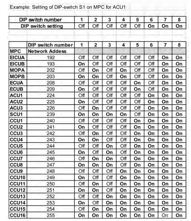
For example, if you are replacing an ACU1 MPC without the ID key, you should set the positions of DIP switch S1 according to the table provided. Refer to the table for the switch positions of ACU1. For instance, if switches 1 through 5 are OFF and switches 6, 7, and 8 are ON, configure DIP switch S1 accordingly.
One important note is that the table above shows which switch numbers are ON and which are OFF. Some instruction books, however, present this information using binary numbers instead of ON/OFF notation in REVERSE ORDER . In such cases, you will need to convert the binary number to the corresponding DIP switch settings. For example, if the table shows the address for ACU1 as binary code 11100000, you need to set DIP switch S1 to 00000111 on the MPC card.
It’s crucial to follow this conversion process correctly, as the binary code and DIP switch sequence may be reversed. Therefore, when setting the address via DIP switch S1, carefully read your instruction book to determine if the address should be entered in order or in reverse order.
After setting up DIP switch S1 according to the manual, you need to set Colored DIP switch No. 5 to OFF. Then, when you turn the power ON, the MPC will download its relevant program without needing the ID key.
New ID Key Programming
Ships often keep a new ID key as an essential spare part. When a new ID key is available, you will need to program it. The ID key programming process involves using the MPC to program the new ID key.
- Power Off the MPC.
- Set DIP switch S1 according to the MPC card’s address, as previously described.
- Do not change the Colored DIP switch.
- Power On the MPC. The MPC will show an ID key error.
- Insert the ID key into the MPC. The MPC will then program the ID key.
Once the programming is complete, the LED will show four red flashes followed by three green flashes, indicating that the ID key programming is finished. At this point, you should revert DIP switch S1 to its original settings.
The LED information table is provided below for reference.
The methods and procedures described for the MPC card are based on my current knowledge. There may be updates to the procedures or variations between engine models. It is best to refer to the Maker’s manual for the most accurate information. It is also advisable to familiarize yourself with the MPC replacement procedures in advance to handle issues more efficiently.
Kyaw Soe Aung (0912 HR, 1 Jul 2024, Yangon)
(This overview of ME Engine Control Systems is intended solely for educational purposes and knowledge sharing. It is not designed for commercial publication or professional use. The information provided aims to offer a general introduction to ME Engine Control Systems for those unfamiliar with the topic.
Please be aware that this overview is based on specific ME engines encountered and reflects current technology as of the date of writing. Due to the evolving nature of technology, there may be gaps, discrepancies, or inaccuracies in the information presented.
For the most accurate and up-to-date information, further research and consultation with industry experts are recommended. Corrections, additional insights, and feedback from the community are welcome to enhance the accuracy and usefulness of this material.)

Leave a comment