Hydraulic System
The ME engine’s hydraulic system is an electronically controlled mechanical hydraulic system. The engine control system manages the engine’s fuel oil injection and exhaust valve operation using hydraulic power. The system uses lubricating oil for hydraulic oil and the Hydraulic Power Supply Unit (HPS) provides the necessary hydraulic oil.
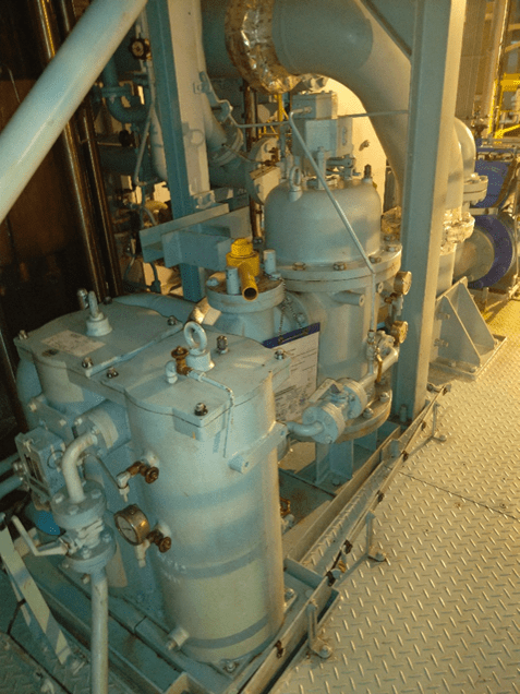
Hydraulic Power Supply Unit (HPS)
The HPS unit includes a filter unit, pumps, a safety valve block, accumulators, a drip pan with a leak sensor, and high-pressure pipes. In auto mode, the engine control system adjusts the hydraulic oil pressure based on the engine load. The HPS supplies hydraulic oil to the Hydraulic Cylinder Units (HCU). Further details about the HCU will be provided later.
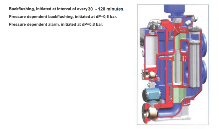
For the ME Engine HPS filter unit, MAN B&W commonly uses Boll and Kanagawa filters. These are similar to the lube oil auto back-flushing filters we’ve seen. The Boll filter is a multiple cartridge filter, while the Kanagawa filter is a single cartridge type. There is also a redundant filter included for backup purposes when maintenance or replacement is needed.
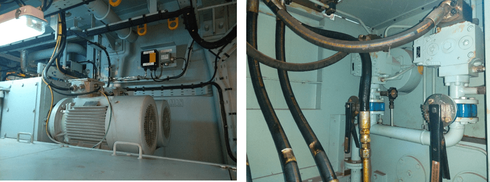
Hydraulic Pump Units
Hydraulic pumps can be divided into two types: electric motor-driven pumps and engine-driven pumps. Electric motor-driven pumps typically number two, while engine-driven pumps can range from three to five, with larger engines sometimes having up to five. The electric-driven pumps provide the necessary hydraulic power when the engine is off or starting. Once the engine is running, the engine-driven pumps supply the hydraulic oil.
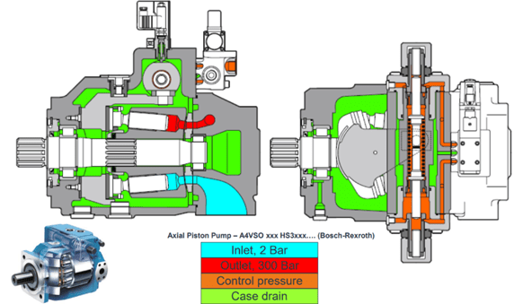
These pumps are generally of the axial piston type. Engine-driven pumps can adjust the flow via the swash plate position, while electric pumps usually have a fixed flow rate.
The Auxiliary Control Unit MPC (ACU) manages the pumps. If there are five engine-driven pumps, the ECU (Engine Control Unit MPC) controls the fourth and fifth pumps. The two electric-driven pumps are designated as master and standby. In auto mode, when the engine switches to standby mode, the master pump remains operational. The standby pump only operates in conjunction with the master pump when pressure needs to be built up.
The operation of the electric-driven pumps varies depending on the engine type and control system:
- Start-Up: When the engine is started and set to standby mode, the electric-driven pumps begin to operate. Once the engine reaches the specified load level, the electric pumps stop.
- Engine Running: If the engine is running and the RPM drops, causing the pressure from the engine-driven pumps to decrease, the electric pumps will operate alongside the engine-driven pumps to maintain pressure.
- Shutdown: When the engine command to stop is given, the electric pumps will cease operation.
- Variable Displacement: Some electric pumps are of the variable displacement type, working in tandem with engine-driven pumps for optimal performance.
Overall, the system ensures that hydraulic power is continuously available under various operating conditions.
Usually, when the engine is off or hasn’t reached a sufficient RPM to build up adequate pressure with the engine-driven pumps, electric pumps are used to maintain adequate hydraulic system pressure. In other words, electric pumps are used when hydraulic oil consumption is lower. As a result, electric-driven pumps are smaller in size compared to engine-driven pumps.

Engine Driven Pump
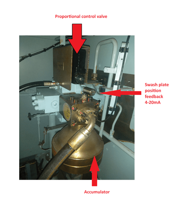
Engine-driven pumps are of the axial piston type, as mentioned earlier. The swash plate position of these pumps is controlled by the ACU MPC through proportional valves. To stabilize hydraulic oil pressure and reduce fluctuations, accumulators filled with nitrogen are installed at the pump outlets. Since the pumps are driven by gear wheels connected to the engine rotation, hydraulic flow depends on both engine speed and swash plate position. Additionally, because the engine can move both ahead and astern, the pumps must be adjusted according to the engine direction. The ACU manages these adjustments.
All engine-driven pumps are identical, and in the event that one pump fails, the remaining two are designed to provide hydraulic power supply up to 66% of the engine load. If there is an electric power failure and the swash plate cannot be controlled, it will default to the maximum ahead direction.

In the Hydraulic Power Supply (HPS) system, there are two working pressure levels: 200 bar and 300 bar. As mentioned earlier, when the HPS is in Auto mode, the engine control system sets the hydraulic pressure set point based on the engine load. During engine operation, the swash plate positions of the engine-driven pumps are controlled according to this set point. There are two control modes for the pumps: Pressure control mode and follow mode.
The pump designated as the control pump operates continuously at 50% capacity and primarily handles sudden pressure fluctuations. When there is a discrepancy between the set point pressure and the actual pressure over time, the remaining pumps in follow mode adjust their positions as needed, while the control pump maintains its 50% capacity.


To protect against increases in hydraulic pressure within the system between the hydraulic pumps and the Hydraulic Cylinder Unit (HCU), safety valve blocks are installed. These include pressure relief valves, check valves, and pressure transducers. Below, I have provided an example of the safety valve block on my current vessel, showing the valve positions in the drawing. The valve positions can be identified in the hydraulic line drawings provided later. However, some valves may not be shown in the drawing.

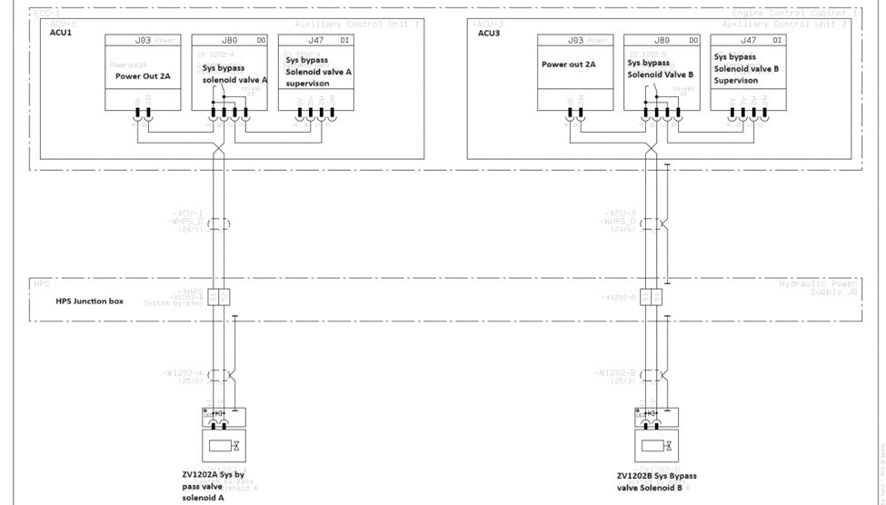
Valve positions 311 and 310 are pressure relief valves. Specifically, positions 310, represented by ZV1202A and ZV1202B, are controlled by ACU1 and ACU3 MPC, respectively. These valves protect the engine-driven pumps from high pressure. When the pressure reaches 310 bar, the ACU will operate the pilot valves to facilitate pressure relief. When these pressure relief valves open, the hydraulic oil will return to the suction side of the engine-driven pumps.
To ensure redundancy, there are two pressure relief valves, with one managed by ACU1 and the other by ACU3. A ball valve (Pos 316) is located nearby to allow adjustment of the valves if needed. Ball valve (Pos 315) is used for draining the system.
Position 311 is a mechanically adjusted pressure relief valve set to open at 315 bar. When this valve opens, if the electric pumps are operating, the hydraulic oil will flow back into the main tank. If the engine-driven pumps are running, the oil will return to the pump suction side.

If, for any reason, oil leaks from the pumps or high-pressure pipes, it will reach the drain pan through the drain pipe located under the pump cabinet. If the leak is minor, the oil will continue to flow into the main tank through the drain pan. However, if the leakage is significant, the oil level in the drain pan will rise.
The drain pan is equipped with two level switches. When the high-high level switch in the drain pan is activated, the engine will be shut down. Since there may be other leak detection systems in place related to hydraulic oil leaks, it is important to carefully read the alarm names if an alarm is triggered.
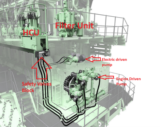
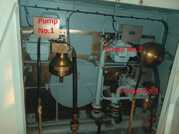

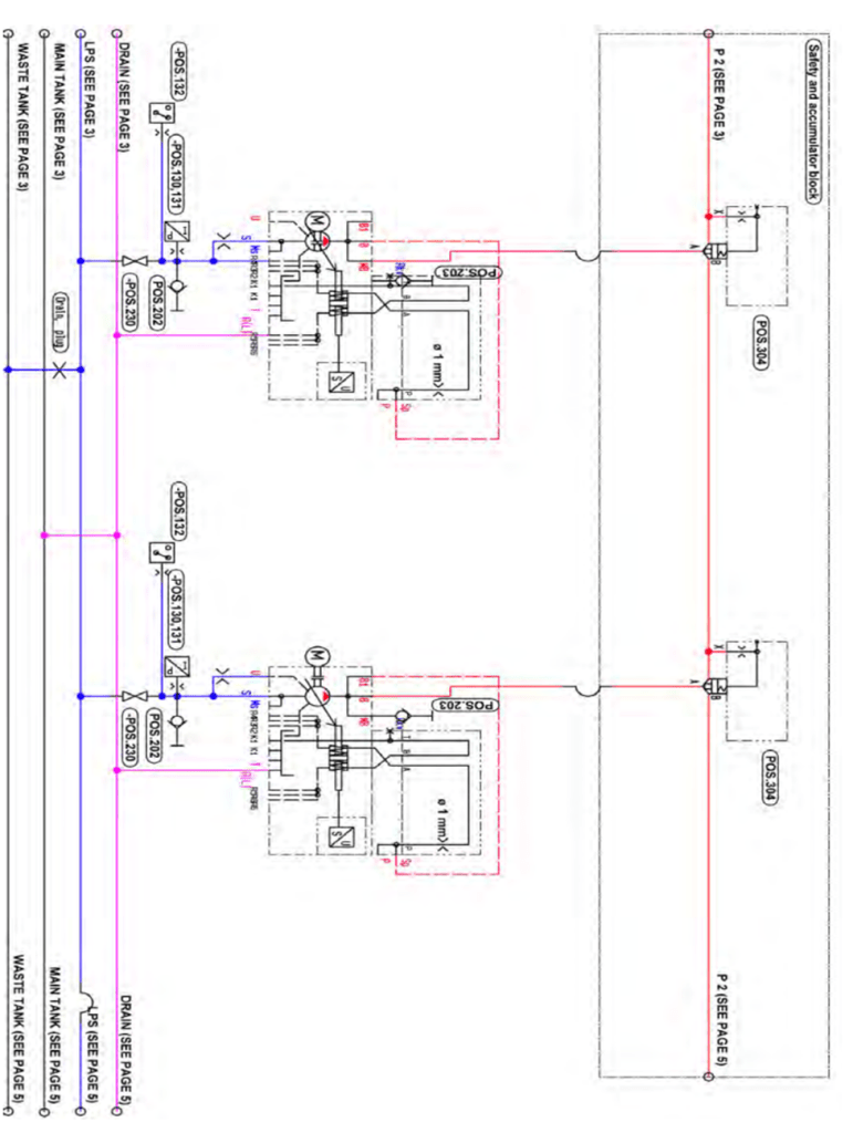
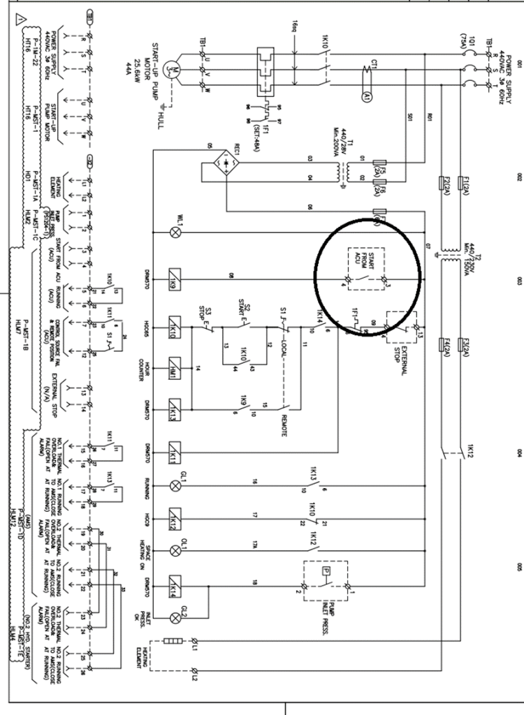
Figure 49 Electric Motor Driven Pumps Hydraulic Diagram
References
1) Hyundai-Man B&W Diesel Engine Main Engine Manual Volume II
2) MAN Diesel PrimeServ Academy
(This overview of ME Engine Control Systems is intended solely for educational purposes and knowledge sharing. It is not designed for commercial publication or professional use. The information provided aims to offer a general introduction to ME Engine Control Systems for those unfamiliar with the topic.
Please be aware that this overview is based on specific ME engines encountered and reflects current technology as of the date of writing. Due to the evolving nature of technology, there may be gaps, discrepancies, or inaccuracies in the information presented.
For the most accurate and up-to-date information, further research and consultation with industry experts are recommended. Corrections, additional insights, and feedback from the community are welcome to enhance the accuracy and usefulness of this material.)

Leave a comment