Hydraulic Cylinder Unit (HCU)
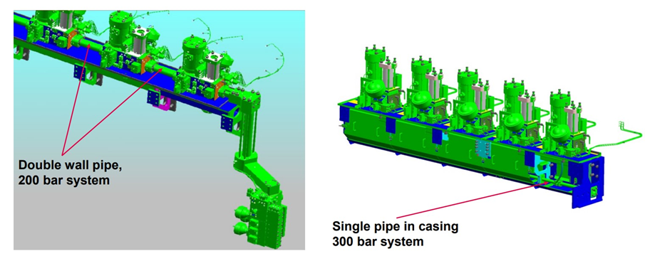
The Hydraulic Power Supply Unit supplies hydraulic oil to the HCU through double-wall hydraulic pipes. If single-wall pipes are used instead of double-wall pipes, the hydraulic pipes are typically housed within a casing. There are systems with pressures of 300 bar as well as systems with 200 bar. The Hydraulic Cylinder Unit (HCU) contains one cylinder unit per unit. However, as an exception, the ME-B model uses one HCU for two cylinder units.

A Hydraulic Cylinder Unit consists of:
- Distribution Block
- FIVA (Fuel Injection Valve Actuator)
- Fuel Booster
- Exhaust Valve Actuator
- Lubricator
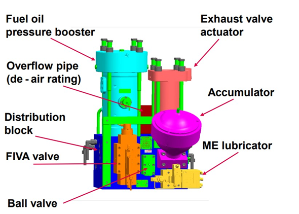

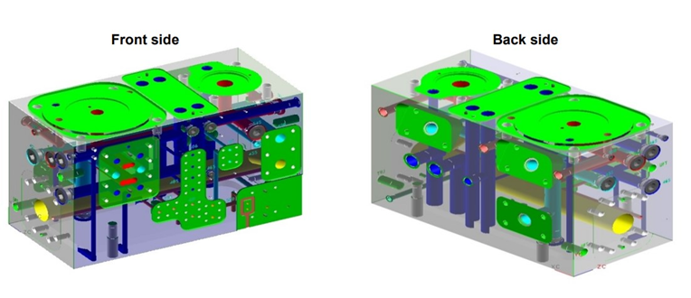
The distribution block distributes hydraulic oil to the FIVA valves. It also has valves to isolate hydraulic oil when removing or servicing the HCU. When performing maintenance on the HCU, it’s essential to read and follow the maker’s instructions carefully to properly isolate the system. An instruction plate is often attached to the HCU block as well.
To ensure consistent and stable hydraulic pressure during the operation of the fuel booster and exhaust valves, an accumulator filled with nitrogen is installed in the distribution block. This helps maintain stable pressure levels.
The accumulator functions similarly to a hydrophore. It contains a bladder filled with nitrogen. At the top of the accumulator, there is a poppet valve for the hydraulic oil to enter and exit. When there is no hydraulic oil in the accumulator, the nitrogen expands within the bladder, keeping the poppet valve closed. As hydraulic oil enters the accumulator, it forces the nitrogen bladder to compress, and the oil enters the accumulator through the poppet valve.
When the hydraulic oil pressure matches the nitrogen pressure, the oil flow stops, and the accumulator maintains a balanced pressure. If the system pressure drops, the nitrogen bladder expands, pushing the hydraulic oil out of the accumulator. The oil is expelled until the pressure inside the system returns to match the nitrogen pressure. Once the system pressure rises again, the nitrogen bladder compresses, and the hydraulic oil flows back into the accumulator.


On the distribution block, you will also find the FIVA valve (Fuel Injection Valve Actuation). The FIVA valve controls the hydraulic oil pressure needed to operate the fuel booster and the exhaust valve actuator by regulating the opening and closing of the valve. As mentioned earlier, while there is typically a single FIVA valve, it is sometimes divided into separate components like ELFI (Electronic Fuel Injection) and ELVA (Electronic Valve Actuation). In the case of ME-B, since the exhaust valve is operated by the camshaft, only the ELFI is present. For now, we will focus on explaining the FIVA valve.

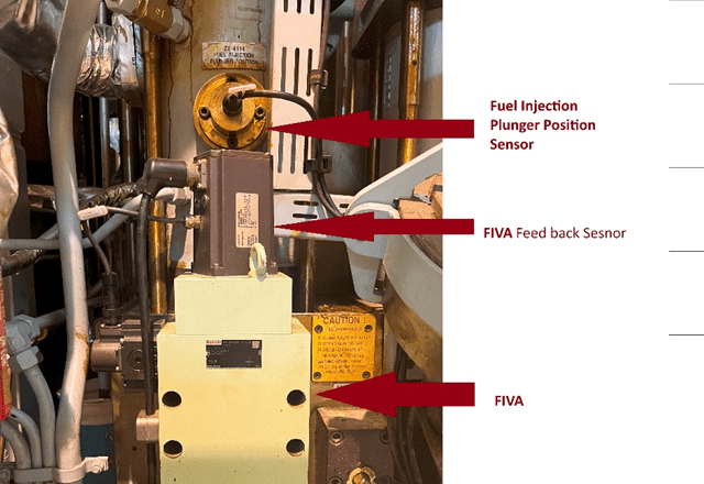
The FIVA assembly includes the main FIVA valve and a pilot control valve responsible for its operation. Additionally, a feedback sensor is integrated into the system to relay the FIVA position information back to the Engine Control System via the CCU MPC. FIVA valves are manufactured by several companies, including MAN B&W, Bosch Rexroth, and Nabtesco. Similarly, pilot control valves are produced by various manufacturers such as MOOG, Parker, Bosch Rexroth, and Nabtesco.
Although I haven’t worked extensively with FIVA systems, the maker’s instruction manuals indicate that Bosch Rexroth pilot control valves cannot be easily removed and replaced. In the Nabtesco FIVA systems I’ve encountered, the feedback sensor and pilot control valve are distinct components and are wired separately. Currently, the vessel I’m working on is equipped with a Bosch Rexroth FIVA system, where the wiring leading to the FIVA is connected to the feedback sensor, while the pilot control valve is linked through this sensor.
The instruction manual also notes that if the FIVA feedback sensor needs to be removed, a calibration tool is required for reinstallation, and this should be performed by a service technician. I have not yet encountered this situation personally.
Despite variations among manufacturers, the fundamental operational principles of FIVA systems remain consistent. The CCU’s Tacho System determines the timing for fuel injection and exhaust valve operations. The ECU provides the fuel index, based on which the FIVA’s pilot control valve receives commands for fuel injection and exhaust functions. The pilot control valve, following the CCU’s commands, adjusts its spool, which then drives the main spool of the FIVA to control the fuel booster and exhaust actuator.

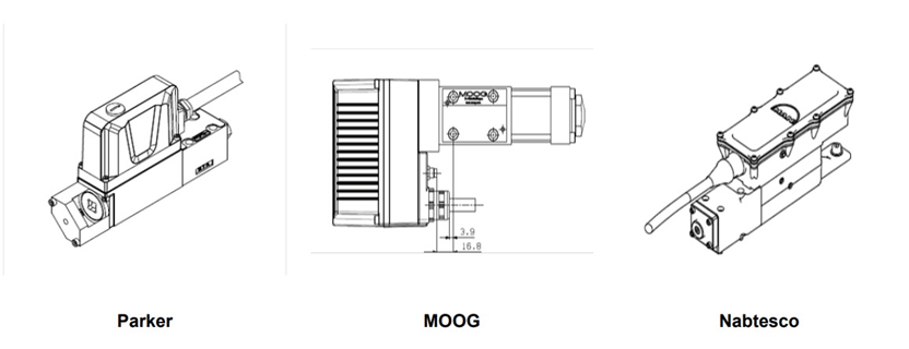

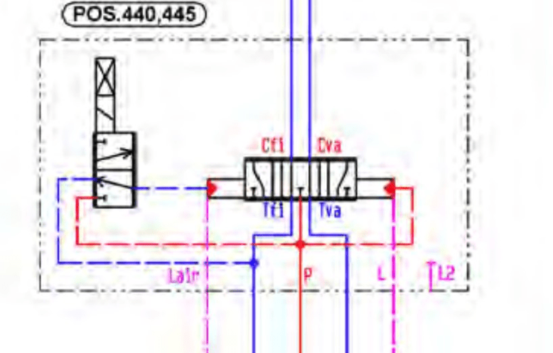
Figure 55 shows the cross-sectional view of a MAN FIVA valve, which uses a Parker pilot control valve. Hydraulic oil enters the FIVA through port P, driven by system pressure. Based on the signal received from the CCU, the pilot control valve moves its pilot spool, which in turn shifts the main spool of the FIVA according to the system pressure.
When fuel injection occurs, the main spool directs the high-pressure hydraulic oil from port P to port Cfi. At this moment, the hydraulic oil flowing to the exhaust valve actuator will return from Cva to Tva and then to the tank. Similarly, when the exhaust valve needs to open, the main spool redirects the high-pressure hydraulic oil from P to Cva to actuate the exhaust valve actuator. During this time, Cfi and Tfi will be open, allowing the fuel booster to return oil to the tank via gravity.
Since the FIVA main spool moves up and down, lubrication is necessary. Hydraulic low-pressure oil enters through port L to lubricate the FIVA spool. Figure 56 illustrates the hydraulic diagram of the FIVA valve.

The CCU needs to not only send commands to the FIVA but also to monitor the position of the FIVA valve. For this purpose, a Linear Variable Differential Transformer (LVDT) is used for feedback sensing.
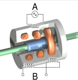
An LVDT (Linear Variable Differential Transformer) is a type of sensor used to detect linear displacement or movement. It consists of a primary winding and two secondary windings arranged in opposition to each other. Because of this configuration, when the ferromagnetic core is positioned centrally between the two secondary windings, the induced voltages in the secondary windings are equal but have opposite polarities, resulting in an output voltage of zero.
If the core moves toward one of the secondary windings, the induced voltage in that winding increases, while the voltage in the other winding decreases. Consequently, the output voltage of the LVDT changes according to the movement of the FIVA main spool. This output voltage is then converted into a current signal and sent to the CCU. As mentioned earlier, the LVDT requires calibration if it is removed and reinstalled, and this procedure should be performed by a service technician, as indicated in the manual.

© KSA

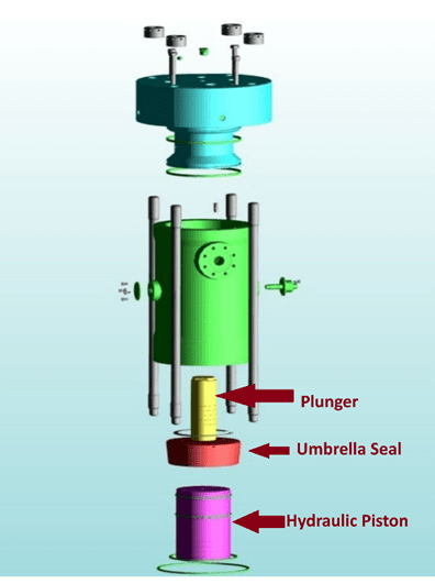
When the CCU sends a fuel injection command to the FIVA, the Pilot Control Valve adjusts the position of the FIVA valve main spool (P to Cfi) according to the fuel injection profile. Hydraulic oil, under system pressure, reaches the fuel oil booster and pushes the hydraulic piston upwards. This action moves the plunger and delivers fuel oil into the fuel injector. During this process, the accumulator helps stabilize the pressure. Figure 60 shows that the fuel oil enters the fuel oil booster at a pressure of 10 bar. After fuel injection, the FIVA valve closes the (P to Cfi) line and opens the (Cfi to Tfi) line, allowing the hydraulic oil to return through the return line. At this time, the fuel pressure remains at 10 bar, and gravity causes the hydraulic piston to move downward.
The Engine Control System needs to monitor the position feedback of the hydraulic piston to manage fuel delivery accurately. Therefore, a fuel oil booster feedback sensor is installed, which uses an inductive sensor to determine position. An umbrella seal is placed at the top of the plunger to ensure precise movement tracking. The seal has a broad side and a narrow side, creating a shape that allows the inductive sensor to detect changes in distance as the plunger moves up and down. This position feedback is then sent to the Engine Control System.

High-pressure fuel oil pipes that experience leaks will direct the leaked fuel oil through the drain pipe of the fuel oil booster unit. If the leakage becomes significant, the pressure within the fuel oil booster will increase, activating the pressure switch at the top of the booster. While MC engines typically have only one fuel oil leakage alarm, ME engines are equipped with leakage detection systems for each hydraulic cylinder unit.

Exhaust Valve Actuator
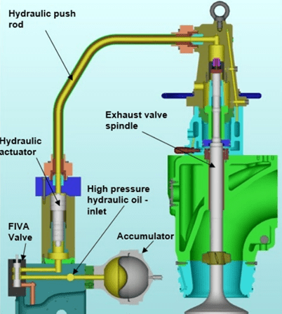
When the CCU sends an exhaust valve opening command to the FIVA pilot control valve, the FIVA valve opens the (P to Cva) line, allowing hydraulic oil to flow to the exhaust valve actuator. This hydraulic oil then actuates the hydraulic actuator. The hydraulic pressure affects the exhaust valve spindle inside the exhaust valve, causing the exhaust valve to open.
To close the exhaust valve, FIVA opens the (Cva to Tva) line, and the hydraulic oil in the exhaust valve actuator returns to the return line. The hydraulic actuator then moves downward due to gravity. The exhaust valve is designed to have an air supply and an air spring effect, so when hydraulic pressure is not present, the exhaust valve spindle returns to its original position using the air spring effect.
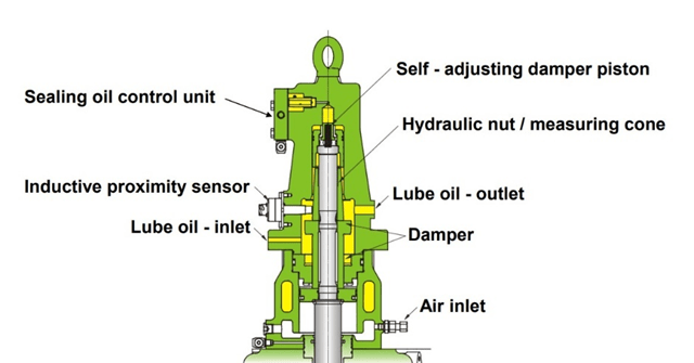
Just like the fuel oil booster feedback sensor, an inductive sensor is used for exhaust valve spindle position feedback as a proximity sensor. The position of the exhaust valve spindle is detected through a hydraulic nut/measuring cone. This sensor also features an umbrella seal design similar to that of the fuel oil booster unit, with one side narrow and the other side wide. The distance between the inductive sensor and the measuring cone changes according to the spindle’s position, which allows the sensor to determine the position of the exhaust valve spindle.
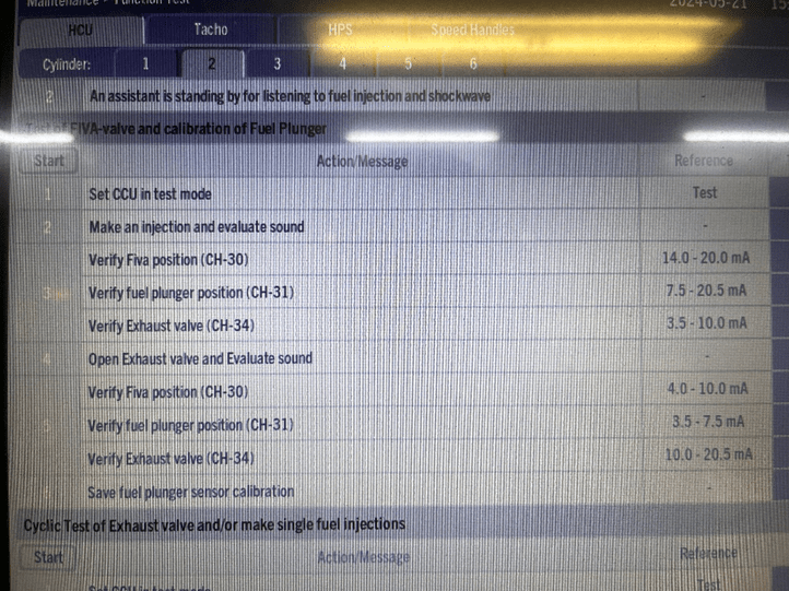
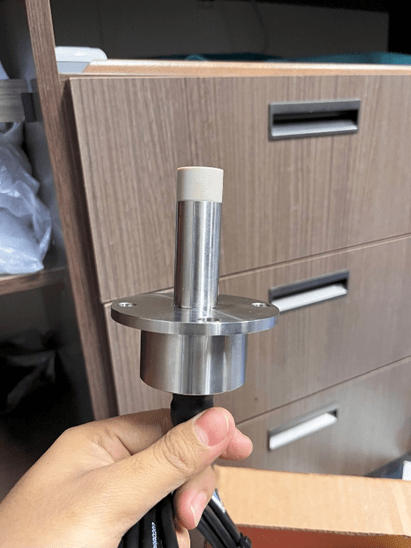
The fuel oil pressure booster and the exhaust valve both use inductive sensors, which, based on my experience, are similar in design but differ only in length. If you need to replace them, be sure to cross-check the part numbers. From what I’ve encountered, simply removing and replacing the sensors doesn’t typically require recalibration. However, the manual suggests that if you disassemble mechanical parts and perform an overhaul, you should calibrate the sensors. In the MOP panel, you can perform a function test by going to Maintenance – Function Test – HCU. The system will verify the sensor values. Before doing so, it’s essential to thoroughly read the instructions in the manual. The main engine manual may not always have the required sections readily available, so it’s helpful to search for and note the necessary information in advance.
References
1) Hyundai-Man B&W Diesel Engine Main Engine Manual Volume II
2) MAN Diesel PrimeServ Academy
(This overview of ME Engine Control Systems is intended solely for educational purposes and knowledge sharing. It is not designed for commercial publication or professional use. The information provided aims to offer a general introduction to ME Engine Control Systems for those unfamiliar with the topic.
Please be aware that this overview is based on specific ME engines encountered and reflects current technology as of the date of writing. Due to the evolving nature of technology, there may be gaps, discrepancies, or inaccuracies in the information presented.
For the most accurate and up-to-date information, further research and consultation with industry experts are recommended. Corrections, additional insights, and feedback from the community are welcome to enhance the accuracy and usefulness of this material.)

Leave a comment