Tacho System
In the previous sections, we discussed the MPC, Hydraulic Power Supply (HPS) Unit, and Hydraulic Cylinder Unit. The MPC units handle control and monitoring based on their respective functions, the HPS provides the necessary hydraulic oil pressure for control functions, and the HCUs manage exhaust valve operation, fuel injection, and cylinder lubrication. To perform these functions, it is essential to know the crankshaft position, and this is the responsibility of the Tacho system.
The Tacho system consists of two units: Tacho A and Tacho B. Tacho A receives power from ECU A and sends the tacho signal to ECU A. Tacho B receives power from ECU B and sends the tacho signal back to ECU B. Additionally, both Tacho A and Tacho B transmit the tacho signal to the CCUs. If one of the Tacho systems fails, the remaining unit will continue to provide the crankshaft position to the CCU and ECU. However, if both Tacho systems fail, it will not be possible to determine the crankshaft position, leading to an inability to perform fuel injection or exhaust valve operation, which will result in an engine shutdown.
Each Tacho system includes an Angle Encoder and an Amplifier. The Angle Encoder is installed on the crankshaft pin connected to the crankshaft. This pin is located at the front of the engine, with Encoder A mounted on the engine and Encoder B positioned externally. Therefore, if Encoder A needs to be replaced, Encoder B must also be removed. The encoder pin has a central hole, and the encoder itself is mounted on the crankshaft pin. To reduce vibration, flexible rings are placed between the encoders.

Encoder Construction
Both Encoder A and Encoder B have the same construction. Each encoder consists of two parts: a stationary part and a rotating part. The rotating part is mounted on the crankshaft pin, as mentioned earlier. The stationary part includes two Marker sensors and two Quadrature sensors. The difference between Encoder A and Encoder B is the position where the rotating part is mounted on the crankshaft.
Let’s use Encoder A as an example. Figure 76 illustrates Encoder A. In the stationary part, you will find Marker Master A (MMA), Marker Slave A (MSA), Quadrature 1 A (Q1A), and Quadrature 1 B (Q2B). The rotating part includes a semi-circular ring and a gear wheel with 360 teeth. MMA and MSA are responsible for sensing the semi-circular ring, while Q1A and Q2B detect the teeth on the gear wheel. MMA and MSA are positioned 90 degrees apart.
When the No.1 cylinder reaches 0 degrees TDC (Top Dead Center), MMA initially detects the semi-circular ring. It continues to detect it until 180 degrees ATDC (After Top Dead Center). Between 90 degrees ATDC and 270 degrees (90 + 180 degrees) ATDC, MSA detects the semi-circular ring. When a new encoder is installed, the encoder’s shaft must be rotated and adjusted to achieve this detection pattern. Further details will be explained later.

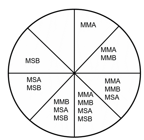
The Marker Master A (MMA) and Marker Slave A (MSA) sensors detect the semi-circular ring to provide an approximate position of the crankshaft. For example, if MMA is ON and MSA is OFF, the crankshaft is between 0 degrees TDC (Top Dead Center) and 89 degrees ATDC (After Top Dead Center) for cylinder No.1. When both MMA and MSA are ON, it indicates a position between 90 degrees and 179 degrees. To determine the precise position in degrees, the Quadrature sensors are responsible for providing the exact measurement.
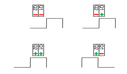
The rotating part of the encoder includes a semi-circular ring and a gear wheel with 360 teeth, as previously described. The encoder is equipped with two Quadrature sensors. These sensors detect the gear teeth and are ON when they register the presence of a gear tooth. Since the gear wheel has 360 teeth, the distance between each gear tooth is 1 degree. Figure 77 shows that the two Quadrature sensors can detect increments as small as 1 degree, with detailed measurement capability extending up to four positions per degree.
When the engine is stopped, the Engine Control System does not yet know the crankshaft position. During the engine startup process, air is run to initiate the engine, and after 3-4 revolutions, the Marker Master A (MMA) on the encoder begins to detect the semi-circular ring and starts counting. At this point, the Quadrature sensors also start counting the number of gear teeth passed. This method allows the Engine Control System to precisely determine the crankshaft’s angular position in degrees, enabling the initiation of fuel injection and exhaust valve operations.

Encoder B operates in the same manner as Encoder A. It also features two Marker sensors and two Quadrature sensors. These are designated as Marker Master B (MMB), Marker Slave B (MSB), Quadrature 1 B, and Quadrature 2 B. The Marker sensors in Encoder B are positioned at 45 degrees ATDC (After Top Dead Center) and 135 degrees ATDC (45 + 90 degrees) relative to Cylinder No. 1. Consequently, as the crankshaft rotates, MMB will be ON between 45 degrees and 134 degrees ATDC. When both MMB and MSB are ON, the crankshaft position will be between 134 degrees and 225 degrees ATDC. Figure 79 illustrates how the Marker sensors activate according to the crankshaft degree position for Cylinder No. 1.
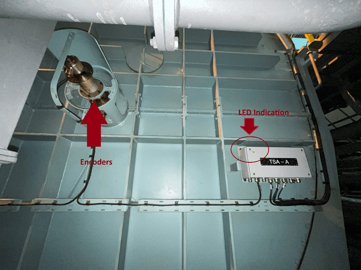
The encoders send Tacho signals to the CCU and ECU MPC units through the Amplifier units. The Amplifier units are designated as TSA-A and TSA-B. Encoder A is connected to TSA-A, while Encoder B is connected to TSA-B. When the Marker Master sensors in the encoders activate, the corresponding LED lights on the amplifier boxes will illuminate.
As previously discussed, the Marker sensors activate once during a full 360-degree rotation. For example, consider Marker Master A: it starts to activate at 0 degrees TDC (Top Dead Center) for Cylinder No. 1 and continues to activate until it has passed the semi-circular ring, up to 180 degrees ATDC (After Top Dead Center). After 180 degrees ATDC, it remains OFF until it reaches the next 0 degrees TDC. Each time the LED on TSA-A lights up, it indicates that the MMA (Marker Master A) has activated once.
In addition to the encoders, a semi-circular ring is installed on the engine flywheel, and a Reference Marker sensor is placed at the 0 degrees TDC (Top Dead Center) position of Cylinder No. 1. This sensor is used to cross-check the measurements taken by the Marker sensors. It’s important to note that the Engine Control System receives data from the Reference Marker sensor instead of the measurements from the MMA (Marker Master A) of Encoder A.

When a failure alarm related to the encoder occurs, sometimes simply checking and tightening the cable connections can resolve the issue, but there are also cases where the encoder itself is faulty, triggering a failure alarm. If one encoder fails and you continue operating the ship with only the remaining functional encoder, there have been incidents where, eventually, the remaining encoder also fails, causing the engine to shut down and resulting in an off-hire situation. Encoder units are critical, so many ships carry spares. If replacement is necessary, it should be carried out promptly and without delay.
Replacing and recalibrating an encoder is not difficult if you understand the placement of the sensors within the encoder, as I previously described. Since Encoder A is mounted close to the engine side, if you need to replace only Encoder A, you will also need to remove Encoder B.
For example, let’s talk about replacing Encoder A. The encoder is mounted on the crankshaft pin and secured with a clamping ring. To replace it, you first need to remove the encoder plug, then loosen the clamping ring, remove the mounting bolts, and pull out the encoder. Since Encoder A has to be removed, Encoder B need to be removed first.
When reinstalling, first mount Encoder A. Before reattaching, ensure that the crankshaft is set to the 0° TDC position. This is necessary because Marker Master A (MMA) of Encoder A turns ON at 0° TDC. Then, install Encoder A. At this point, check the LED on TSA-A to determine whether MMA of Encoder A is ON or OFF.
If the LED is ON during reinstallation, it indicates that the semi-circular ring of Encoder A is positioned between 0° TDC and 180° ATDC. If the LED is OFF, the ring is positioned between 180° ATDC and 0° TDC.
Gradually rotate Encoder A’s shaft in the ahead direction to align the semi-circular ring with the 0° TDC position. If the LED is ON before rotation, when it turns OFF, the semi-circular ring is crossing 180° ATDC. When the LED turns ON again after being OFF, the semi-circular ring has reached 0° TDC.
After this, rotate the Encoder shaft backwards until the LED turns OFF. Once the LED is OFF, stop and then gradually rotate the shaft forward until the LED turns ON again.
After that, securely reattach the clamping ring and proceed to remount Encoder B. When setting up Encoder B, ensure that the crankshaft is positioned at 45° ATDC. This is because Marker Master B of Encoder B turns ON at 45° ATDC. Adjust Encoder B in the same manner as Encoder A was adjusted earlier and then re-secure the clamping ring.
References
1) Hyundai-Man B&W Diesel Engine Main Engine Manual Volume II
2) MAN Diesel PrimeServ Academy
(This overview of ME Engine Control Systems is intended solely for educational purposes and knowledge sharing. It is not designed for commercial publication or professional use. The information provided aims to offer a general introduction to ME Engine Control Systems for those unfamiliar with the topic.
Please be aware that this overview is based on specific ME engines encountered and reflects current technology as of the date of writing. Due to the evolving nature of technology, there may be gaps, discrepancies, or inaccuracies in the information presented.
For the most accurate and up-to-date information, further research and consultation with industry experts are recommended. Corrections, additional insights, and feedback from the community are welcome to enhance the accuracy and usefulness of this material.)

Leave a comment