ERCS is designed to reduce NOx emissions in exhaust gases according to the IMO Tier III requirements that came into effect after January 2016. There are various technologies for reducing NOx, including EGR (Exhaust Gas Recirculation), Selective Catalytic Reduction (SCR), Water in Methanol (LGIM-W), and Low Pressure Gas Engine (ME-GA). Personally, I have only encountered the Selective Catalytic Reduction (SCR) technology.
Even with my limited experience with SCR—having operated it for only about two weeks during my time at sea—it’s important to note that my familiarity with this technology is based solely on one type and the requirements may vary.
Selective Catalyst Reduction
When I first thought of SCR, the term “Silicon Controlled Rectifier” came to mind. I started studying SCR in detail only when I was about to join to a ship equipped with this technology. Since SCR operation is managed by the ME Engine Control System in conjunction with relevant MPCs, I have included it in the ME Engine Control System Overview. As an ETO, my goal is to familiarize myself with the system’s operation, so I will focus mainly on the operational aspects.
SCR (Selective Catalytic Reduction) is a technology used to reduce Nitrogen Oxides (NOx) in engine exhaust gases. NOx includes Nitrogen Dioxide (NO2) and Nitrogen Oxide (NO), which contribute to ground-level ozone formation and acid rain, among other environmental impacts.
SCR works by using a catalyst and a reducing agent to break down NOx in the exhaust gases into nitrogen and water. Common reducing agents include Anhydrous Ammonia (NH3), Aqueous Ammonia (NH4OH), and Urea (CO(NH2)2).
In fact, SCR is not a new technology. It has been used since around 1957 in power plants, boilers, and factories in the US and Japan. Its use in ships began around 1980.
After the IMO Tier III NOx Reduction regulations came into effect in 2016, the use of SCR on ships has become more widespread. SCR can reduce NOx in exhaust gases by over 90%.
How SCR Works
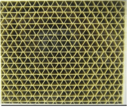
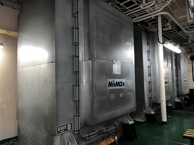
The SCR system I am describing uses Urea as the reduction agent. The SCR system type is Hyundai’s NO NOx, and it uses Pillared Inter-Layered Clay (PILC) as the catalyst. This catalyst is located within the Reactor Chamber.
The Main Engine’s SCR is of the High Pressure type (HP-SCR), while the SCR for the generator engine is of the Low Pressure type (LP-SCR). The difference lies in the placement: HP-SCR is located before the Turbo Charger, whereas LP-SCR is located after the Turbo Charger. However, the NOx reduction principle remains the same for both.
HP-SCR

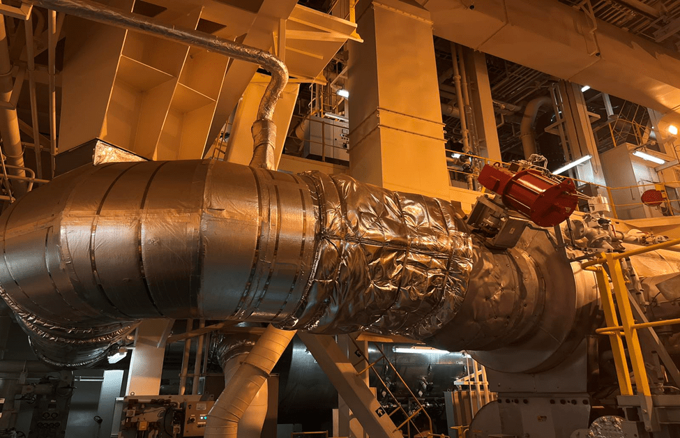
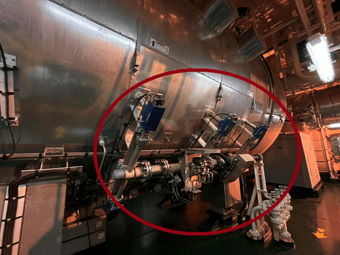
When operating the Main Engine in TIER III mode, the exhaust gases do not enter the Turbo Charger but instead flow directly from the exhaust manifold into the SCR reactor chamber. Before entering the reactor chamber, the exhaust gas line is sprayed with liquid urea via a nozzle from the vaporizer/mixer. The urea is converted into ammonia due to the exhaust gas temperature.
As the exhaust gas, now containing ammonia, enters the reactor chamber, the ammonia reacts with the NOx in the presence of the catalyst, converting the NOx into nitrogen and water. This process reduces the amount of NOx in the exhaust gases exiting the reactor chamber before entering the Turbo Charger and eventually reaching the outer atmosphere.
In the SCR process, the most critical factor is the exhaust gas temperature. Insufficient exhaust gas temperature can lead to the formation of Ammonium BiSulfate (ABS) in the SCR reactor, and if the temperature falls below 200°C, sulfuric acid can condense. Conversely, excessively high exhaust temperatures can increase SO3 formation within the reactor.
SCR Control System
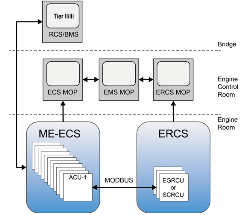
The SCR Control System can be divided into two parts: ERCS (Emission Reduction Control System) and SCR Control Station.
ERCS is provided by MAN B&W and operates in conjunction with the Engine Control System (ECS). The SCR control system discussed here is Hyundai’s NO NOx. It controls both the HP-SCR of the Main Engine and the LP-SCR of the Auxiliary Engines. In the case of LP-SCR, it operates independently, whereas for HP-SCR, it works in conjunction with ERCS.
The ERCS includes two MPCs (Multipurpose Controllers): SCR I1 and SCR CU. SCR I1 is responsible for interfacing with the ERCS MOP (Main Operating Panel) and the ECS (Engine Control System). ECS provides engine load and fuel data to SCR I1, which calculates and determines the necessary temperature values and minimum temperature differences required for the SCR system. SCR I1 then sets the points for opening and closing valves to maintain the required temperature differences within the specified range. It also sets the urea dosing rate.
SCR CU is responsible for operating the valves according to the set points specified by SCR I1. SCR CU receives the set point data from SCR I1, as well as data from pressure and temperature sensors within the system. It then sends the commands for the SCR process to the SCR control station.


SCR Operation
To operate the SCR, the following valves are used:
- Reactor Bypass Valve
- Reactor Throttle Valve
- Reactor Sealing Valve
- Cylinder Bypass Valve
- Exhaust Bypass Valve
If the ship is outside the ECA (Emission Controlled Area) and the main engine is running in TIER II mode, the exhaust gases will bypass the SCR reactor and go directly into the turbocharger. At this time, the Reactor Bypass Valve (RBV) will be 100% open, while the Reactor Sealing Valve and Reactor Throttle Valve will be closed.

To enter the ECA (Emission Controlled Area) and switch to TIER III mode, the SCR system must be prepped before arriving in the ECA. To transition from TIER II to TIER III, the Engine Control must be managed from the ECR (Engine Control Room). Set the telegraph to match the bridge, change the command, and then switch to TIER III from the Engine Control System MOP (Main Operating Panel).
As mentioned above, maintaining the correct temperature in the SCR reactor chamber is crucial for effective reduction. When transitioning to TIER III, the SCR system will initially allow some exhaust gases to pass through the reactor chamber to provide heat before urea dosing begins. The reactor chamber also includes an electric heater to ensure the temperature rises above 200°C.


When switching to TIER III, both the Reactor Sealing Valve (RSV) and Reactor Throttle Valve (RTV) will open. The RSV is a fully open/close type, while the RTV adjusts its position as needed for opening and closing.
To ensure the SCR reactor chamber reaches an adequate temperature, the temperature of the exhaust gases from the manifold to the reactor chamber must stay within the temperature difference range specified by the ERCS. Therefore, the RTV monitors the temperature difference between the SCR chamber inlet and the Turbo Charger inlet, and adjusts its opening and closing accordingly to maintain the required temperature.
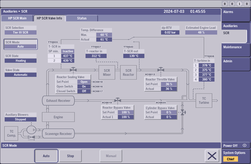
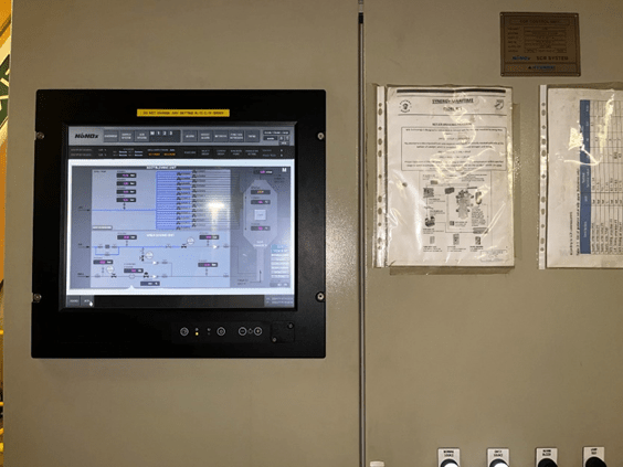
Fig 98 shows the SCR MOP. In this figure, it is evident that the SCR is set to TIER III Auto mode. The SCR state is at Heating. The RTV is open at 36%, while the RBV is fully open at 100%. The Temperature Turbine Inlet is at 378 degrees, and the Temperature SCR out is at 139 degrees. The system specifies that the temperature difference between the SCR inlet and the TC inlet should be below 60 degrees. To achieve this, the RTV is adjusted to maintain this temperature range, and the SCR outlet temperature is increased accordingly.
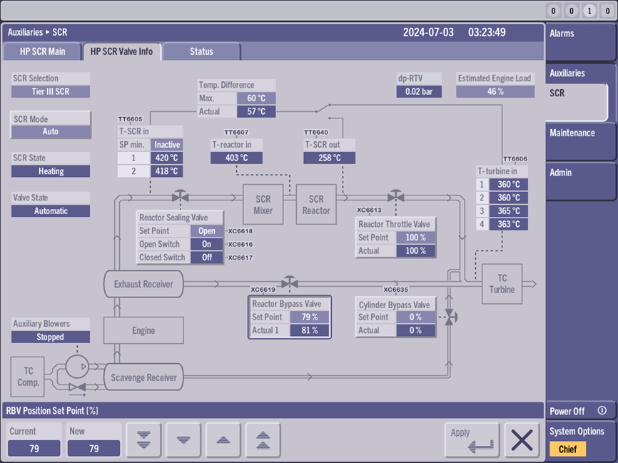
When the SCR outlet temperature increases, the system keeps the RTV open at 100%. At this time, the RBV begins to close.
When the engine is operating at low load and the exhaust gas temperatures are low, there may not be enough heat for the reactor chamber. To address this, a Cylinder Bypass Valve (CBV) is installed. This valve redirects scavenge air away from the cylinder units and back into the Turbo Charger Inlet. When the exhaust temperature is low, the CBV opens as needed to reduce the amount of scavenge air, which helps increase the exhaust gas temperatures. During SCR operation, the CBV adjusts its opening and closing to maintain stable temperature levels despite changes in engine load.

As mentioned above, the Reactor Throttle Valve (RTV) adjusts its operation based on the temperature difference between the SCR inlet and the Turbo Charger (TC) inlet temperatures. When the CBV is open, scavenge air reaches the TC inlet, which can affect the accuracy of the TC inlet temperature measurement. As a result, during this time, the RTV switches to using the SCR outlet temperature instead of the TC inlet temperature. It compares the SCR outlet temperature with the SCR inlet temperature to adjust its opening and closing. This change can be seen on the Toggle switch display on the SCR MOP panel.

The Reactor Sealing Valve, Reactor Throttle Valve, Reactor Bypass Valve, and Cylinder Bypass Valve are all controlled by the SCR-CU MPC (Multipurpose Controller). The SCR-CU MPC is also responsible for managing the temperature setpoints throughout the SCR process. These setpoints are not fixed and vary based on engine running conditions.
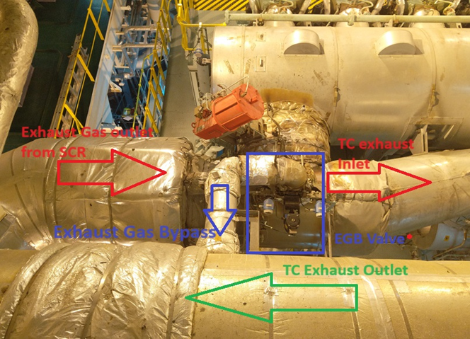
In addition to these valves, another critical valve is the EGB (Exhaust Bypass Valve). Unlike the other valves, the EGB is managed by the Engine Control System’s SCU (Scavenge Control Unit), not the SCR system. During low engine load conditions, the EGB valve remains closed. When the engine load increases, the EGB valve opens to direct exhaust gases away from the turbocharger, routing them directly to the turbocharger outlet. This helps prevent overpressure in the turbocharger and assists in controlling the exhaust gas flow and temperature to the SCR system.
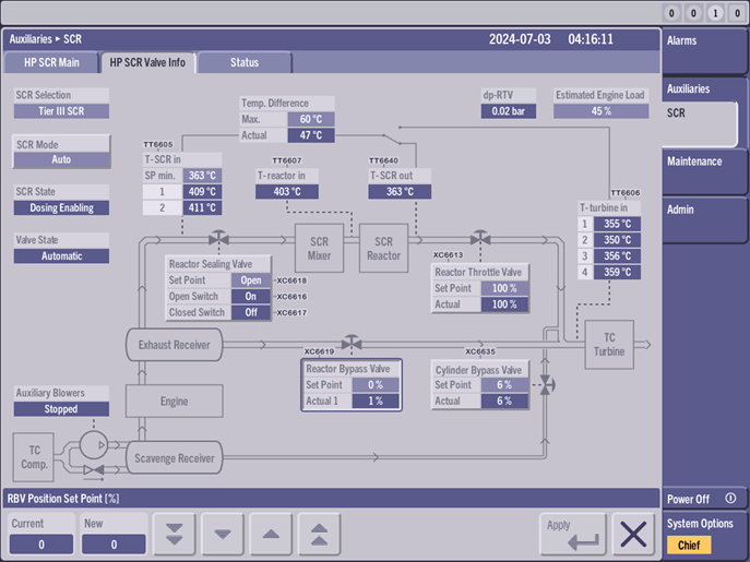
When the Reactor Throttle Valve (RTV) is fully open at 100%, the Reactor Bypass Valve gradually closes completely. At this point, if the temperature going into the reactor becomes excessively high, the Reactor Bypass Valve may open again while the Reactor Throttle Valve closes. Once the temperatures are stable and within acceptable limits, the Reactor Bypass Valve will be fully closed, allowing exhaust gas to flow entirely into the Reactor Chamber. This signifies the start of Urea dosing.
To prevent the formation of soot in the reactor chamber due to exhaust gases, Soot Blower Units are installed. While the Reactor Sealing Valve (RSV), Reactor Throttle Valve (RTV), Reactor Bypass Valve (RBV), and Cylinder Bypass Valve (CBV) are managed by the MAN B&W ERCS’s MPC, the soot blower system is managed by Hyundai’s No NOx SCR control system.
The soot blowing process begins before Urea dosing starts. The soot blower system consists of about 24 units and has a high air consumption rate, which is why there are two SCR compressors installed. If the SCR compressors fail, there is a backup line that draws air from the Main Air Bottle.
The soot blowers operate by sequentially opening the solenoid valves to perform soot blowing. Occasionally, if the valves do not seal properly, there can be air leakage, leading to a constant drop in air bottle pressure. This results in insufficient air for dosing and decreased soot blow air pressure, which can lead to system trips.
Once the temperatures in the SCR chamber are stable, adequate heat is reached, the temperature difference across the SCR system is minimized, and the soot blowing process is completed, Urea dosing begins.
Before starting dosing, the dosing line is cleaned with air pressure. Afterward, the ERCS specifies the dosing rate, and the Urea Dosing Unit dispenses urea through the nozzle according to this rate.


Urea is delivered from the Urea Storage Tank to the dosing station by a pump. At the dosing station, the Urea flow controller, following the Urea dosing rate specified by the ERCS, mixes the urea with air and injects it into the exhaust gas.


As mentioned at the beginning, when urea first comes into contact with the exhaust gas, it transforms into ammonia. This ammonia then enters the reactor chamber, where, with the help of the catalyst, the NOx in the exhaust gas is converted into nitrogen and water. Consequently, the exhaust gas, now with reduced NOx, exits the reactor chamber and enters the turbocharger.
NOx Sensor of HP-SCR
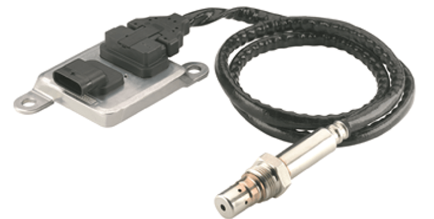
To monitor NOx reduction performance, a NOx sensor is installed at the turbocharger inlet. Due to the high cost and the 2000-hour running limit of the sensor, the vessel I operated used a TIER II sensor, which was replaced with a new one when it failed. For TIER III, a NOx sensor is installed at the turbocharger.
This NOx sensor, originally designed for heavy truck engines, is also compatible with two-stroke engines and meets maritime regulations, according to MAN B&W. Because the sensor is constantly exposed to exhaust gases and has a limited lifespan, two sensors are used. Using two sensors allows for comparison of their values and helps detect sensor drift or failure.
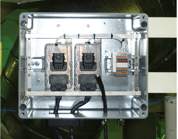
The NOx sensors use CAN bus for data transfer. Since the SCR CU MPC cannot handle CAN bus directly, a PLC control unit is used for signal conversion. The PLC converts the CAN bus signals from the NOx sensors into 4-20 mA signals, which are then sent to the SCR CU.
NH3 Sensor on Main Engine Exhaust Outlet
To detect potential over-dosing of ammonia or if ammonia remains in the reactor chamber without being fully utilized (known as ammonia slip), an ammonia sensor is installed at the main engine’s exhaust outlet. If the ammonia concentration exceeds a set limit, an alarm will be triggered.
On my vessel, a Tunable Diode Laser Spectrometer is used for this purpose. A laser transmitter is installed on one side of the main engine’s exhaust line. Different gases absorb light at specific wavelengths. The laser transmitter emits light at wavelengths tuned to those absorbed by ammonia. This light is then received by a laser receiver on the other side of the exhaust pipe. Based on the received light, the sensor calculates the ammonia concentration.
Occasionally, sensor errors may occur due to dirt on the glasses of the laser transmitter and receiver. Cleaning the glasses with a suitable cleaner usually resolves these issues.


Venting System
When the SCR system is at a standstill, a venting system is installed to prevent the formation of sulfuric acid in the reactor chamber. This system ensures that fresh air circulates through the reactor, preventing backflow of exhaust gases and keeping the reactor clean during periods when the SCR is not in operation. This venting system is present only in the HP-SCR systems and is not installed in LP-SCR systems.

Over Pressure Control
To prevent overpressure within the SCR line, an overpressure control system is installed. This system is found only in HP-SCR systems and not in LP-SCR systems. As mentioned earlier, the Reactor Throttle Valve operates proportionally. To manage the situation where there is a significant pressure difference between the turbocharger and the SCR outlet, the system is designed to open the Reactor Sealing Valve to address the pressure discrepancy.

The Reactor Throttle Valve monitors pressure on one side. If the pressure exceeds the set point, the Reactor Sealing Valve is opened. The recommended value for this set point is between 0.5 and 0.8 bar. If the set point is too low, the Reactor Sealing Valve may intermittently open, causing instability in the SCR operation. Conversely, if the set point is too high, it could compromise SCR safety.

In Fig 116, you can see the pneumatic diagram for SCR over pressure control. In this diagram, the pressure difference between P1 and P2 triggers Valve A. Valve A cuts off the pilot air supply to directional control valves B and C, which control the Reactor Sealing Valve (RSV). The RSV is designed to open to a fail-safe position when control air pressure is lost. Once the pressure is equalized, Valve A deactivates, and pilot air is restored to valves B and C, closing the RSV.
Before entering the ECA, the following should be prepared:
- Reactor Chamber Temperature: As previously mentioned, the reactor chamber temperature should be above 200 ˙C. To reduce the SCR preparation time before entering the ECA, the reactor chamber’s electric heater should be manually turned on for three days.
- Urea Dosing Nozzles: The urea dosing nozzles should be cleaned before entering the ECA.
- Urea Dosing Line Filters: The filters in the urea dosing line should also be cleaned before entering the ECA.

4.Check if the valves in the reactor chamber’s soot blowers are properly sealed and whether there are any air leaks. Also, verify if the SCR air bottle can maintain its pressure and assess if the soot blowers have adequate air supply.


5.DP transmitters are installed to monitor the pressure on each side of the CR valves. If the valves are blocked or the lines are closed, the DP transmitters will trigger an alarm. Occasionally, pressure sensing lines may become obstructed, leading to false alarms, so regular cleaning of the lines is recommended.
6. Since NOx sensors are continuously exposed to exhaust gas flow, regular maintenance and cleaning of these sensors are also necessary.

7. Since SCR is used only in ECA areas, ships that undertake long voyages or operate outside ECA zones may not use SCR for extended periods. In such cases, valves might become blocked or dosing lines might get clogged. MAN B&W recommends regular testing and operation of the system to prevent such issues.
LP-SCR
LP-SCR is installed downstream of the turbocharger exhaust outlet . Compared to HP-SCR, it is simpler in design. However, the principle remains the same. Unlike HP-SCR, it is not integrated with ME’s ERCS (Emission Reduction Control System) but is directly controlled by Hyundai’s NO-NOX system.

Before entering the SCR chamber, there are two valves: the Reactor Bypass Valve (RBV) and the Reactor Sealing Valve (RSV). The RBV allows exhaust gases to bypass the chamber and be released directly into the atmosphere, while the RSV ensures that exhaust gases pass through the chamber before exiting.

Upon entering the ECA and starting the SCR system for the auxiliary engine, the system will open the Reactor Sealing Valve (RSV) and close the Reactor Bypass Valve (RBV). This allows the exhaust gas flow to pass through the chamber and heats up the reactor initially. Once sufficient temperature is achieved (for example, 330°C on my vessel) and the engine load is above 10%, the Urea dosing begins and the NOx reduction process starts.
Air Waste Gate Valve
As previously mentioned, maintaining an adequate SCR reactor temperature is crucial for NOx reduction. In HP-SCR systems, the Cylinder Bypass Valve (CBV) and Exhaust Bypass Valve (EGB) manage the reactor temperature. In the case of LP-SCR systems, this function is performed by the Air Waste Gate (AWG) valve.

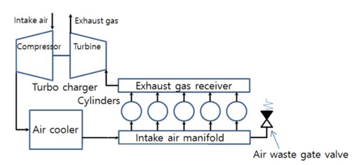
The Air Waste Gate (AWG) valve diverts intake air from the air cooler to outside, bypassing the turbocharger. This process lowers the charge air pressure, which in turn increases the exhaust gas temperature. This mechanism is useful for raising the exhaust gas temperature for SCR operation, while also protecting the turbocharger from excessive charge air pressure.
NOx sensor of LP SCR
The NOx sensor used in the LP-SCR is Danfoss’s IXA model. This sensor can measure SO₂, NH₃, and NOx, but it is used here specifically for NOx measurement. It operates by passing ultraviolet light through the exhaust gas to measure NOx levels. In this type of sensor, compressed air is crucial for both cooling and sealing.


References
1) Hyundai-Man B&W Diesel Engine Main Engine Manual Volume II
2) MAN Diesel PrimeServ Academy
(This overview of ME Engine Control Systems is intended solely for educational purposes and knowledge sharing. It is not designed for commercial publication or professional use. The information provided aims to offer a general introduction to ME Engine Control Systems for those unfamiliar with the topic.
Please be aware that this overview is based on specific ME engines encountered and reflects current technology as of the date of writing. Due to the evolving nature of technology, there may be gaps, discrepancies, or inaccuracies in the information presented.
For the most accurate and up-to-date information, further research and consultation with industry experts are recommended. Corrections, additional insights, and feedback from the community are welcome to enhance the accuracy and usefulness of this material.)

Leave a comment