As an Electrical Cadet on board the ship, I once asked how the ship’s clocks synchronize with each other. Now that we’re dealing with a 24VDC low insulation issue affecting the ship’s clock, I realize I wasn’t able to fully understand or address it properly back then.

Before discussing the ship’s clocks, let me briefly explain about the quartz clocks that we are familiar with.
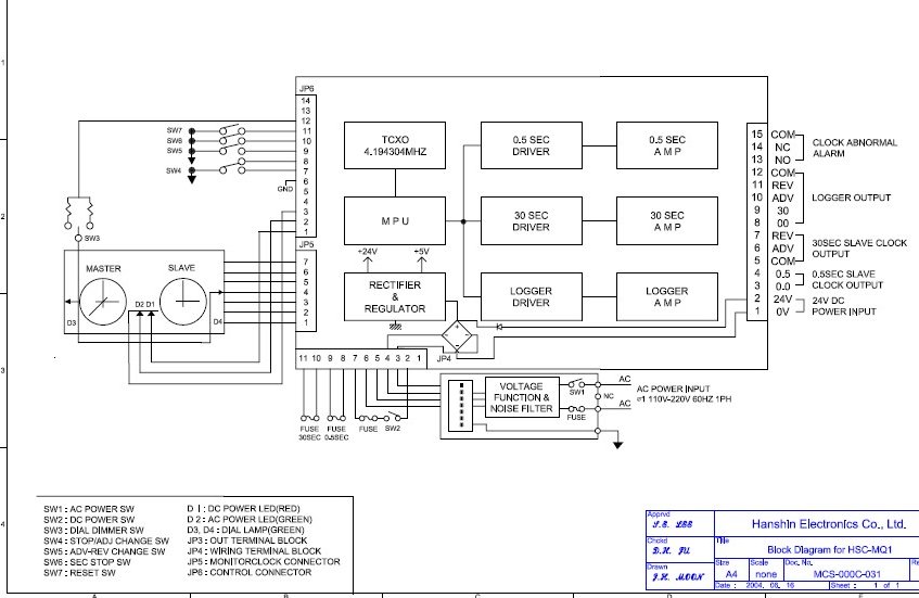
The key component for accurate timekeeping in clocks is the quartz crystal. Typically, a microchip circuit powered by a battery causes the quartz crystal to oscillate at a specific frequency. The microchip detects these oscillations and generates electric pulses at a rate of one pulse per second. These pulses drive a small electric stepping motor, which moves the second hand of the clock. This movement, in turn, drives the gear wheels that move the minute and hour hands.
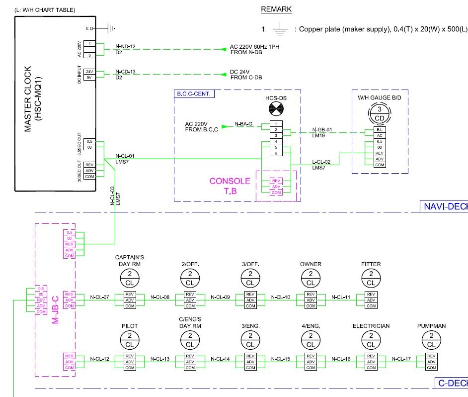
On the ship, the clock system is divided into two types: Master and Slave. The Master clock is always set to UTC, while the Slave clocks are set to the local time zone where the ship is currently located. Both the Master and Slave clocks use a single Main Oscillation PCB to generate electrical pulses, without individual oscillation crystal circuits for each clock. This Main Oscillation PCB sends out the pulses to move the hands of the clocks.

The construction of the Master Clock is similar to that of a standard home clock, except it lacks a separate oscillation circuit. The Main Oscillation PCB generates electrical pulses to drive the clock’s hour, minute, and second hands.
For the Slave clocks, the Main Oscillation PCB provides three contacts: Advance, Retard, and Common. These contacts are used to connect the clocks one by one, allowing all the ship’s clocks to move together. These three contacts essentially function like relay contacts. To move the clocks forward, power is supplied from the Advance and Common contacts. To move them backward, power is supplied from the Retard and Common contacts.
Depending on the type of clock, those with a second hand receive electrical pulses at a rate of once every 0.5 seconds, while clocks without a second hand receive pulses at a rate of once every 30 seconds. Therefore, clocks with a second hand (such as those in the CCR, ECR, and GALLEY) have a dedicated, fine wire provided on the PCB for electrical pulses. Clocks without a second hand receive electrical pulses every 30 seconds from the Advance and Common contacts.
To enable Advance and Retard functions, Slave clocks are equipped with two coils: one for forward direction and one for reverse direction. One coil is connected to the Advance and Common contacts to move the clock forward. The other coil is connected to the Retard and Common contacts to move the clock backward. When the ship’s time needs to be advanced, electrical pulses are continuously sent from the Advance and Common contacts to ensure all Slave clocks move forward simultaneously. Conversely, if the time needs to be set back, power is supplied from the Retard and Common contacts to move the clocks backward. Additionally, the Main Oscillator PCB also provides a 30-second time signal pulse for the Engine Telegraph Order Printer.

Problems Encountered with the Ship’s Clock System
When I first boarded the ship, I found that, except for the Master clock, the remaining clocks were not working properly. Only the Master clock was functioning normally, while the others were either stopping or running irregularly. The previous crew member had ordered a new Oscillation PCB, suspecting it might be the issue.
When the new PCB arrived and I checked it, the situation didn’t improve. Since the Master clock was working fine, I considered that the issue might not be with the Oscillation PCB. I isolated all the clocks on the ship and tested them by connecting only one Slave clock with the Master clock, but the problem persisted. Finally, I discovered that the only component capable of stopping the Slave clocks was the Advance/Stop/Retard selector switch. When I removed the wire from this switch, all the clocks resumed functioning normally, indicating that the problem was resolved.
Another issue I encountered was with 24 VDC low insulation.One afternoon, while investigating a 24VDC low insulation problem, I noticed that the ship’s clocks had stopped working. After removing the fuses from the distribution panel to the ship’s clock system, I found that the insulation issue improved.
From my experience, locating low insulation problems is easier if you understand the ship’s machinery and the behavior of the crew. For example, if there’s a 220V insulation failure, knowing whether it happens during the day or night, whether extension cords are used in the engine room, or if it occurs in accommodation areas where people might be present, helps. Additionally, knowing who recently bought phone chargers, adapters, or electronic devices at the last port can also be useful.
In this case, since the 24V low insulation issue was affecting the clocks, I suspected it was related to a particular cabin. Upon inspection, I found that the clocks’ wires had been cut with a wire cutter. The cut wires were grounded. The person who made these cuts had recently left the ship.
Although the design is relatively simple, if it doesn’t work properly, it can cause timing errors and affect everyone’s schedules on the ship. I’ve shared my experiences with such issues. Depending on the manufacturer, there may be some variations, and if there are specific needs or if guidance is required, please feel free to ask for help as usual. I’m happy to provide assistance as needed.
July 19,2022
(The ship’s clock system I have described is based on my personal experience. Technology is continually evolving, and there may be updated systems currently in use. Please keep in mind that there could be differences or improvements in newer systems.)

Leave a comment