In the introduction of ME Engine Control System, I wrote about the ME Engine Control System, under the MPC cards section, I briefly mentioned the LDCL system as part of the Cooling Water Control Unit (CWCU) MPC card.
Recently, while troubleshooting to restart the LDCL system on the ship that has been stopped for a long time, I decided to write more about the LDCL control.
The troubleshooting itself wasn’t anything special, but since I followed the LDCL control process from start to finish, I wanted to share my experience.
What is LDCL used for?
The sulphur in the fuel oil combines with oxygen during the engine’s combustion process to form Sulphur Dioxide (SO2). Then, SO2 reacts further with oxygen to become Sulphur Trioxide (SO3).
When the SO3 meets moisture from the scavenge air (water vapor), it forms Sulphuric Acid (H2SO4).
Inside the engine, the dew point of H2SO4 is around 150°C to 200°C. When the ship runs at low RPM or low ME load, the cylinder liner temperature drops. If it goes below the dew point of H2SO4, the acid condenses on the liner, causing cold corrosion.
Cold corrosion shortens the life of the liner and piston rings and increases cylinder oil consumption, causing many problems.
To prevent this, the liner jacket water temperature must be kept higher at low RPM. The LDCL system controls and adjusts the liner jacket water temperature based on the ME load to protect the engine.

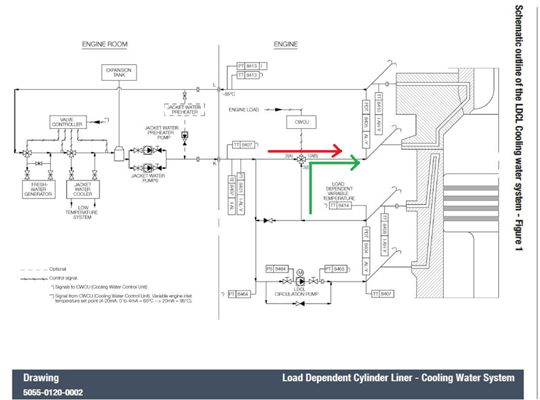
In Figure 1, the red line (TLDVT) shows the Liner Jacket Water temperature. You can see it stays at around 120°C up to 50% ME load. Normally, the ME Jacket Water Outlet temperature is kept steady at about 85°C. The Inlet temperature (Tin) is adjusted according to the ME load. The Liner Jacket Water is circulated inside the liner repeatedly to keep the temperature around 120°C.

In Figure 2, the normal jacket water inlet and outlet are shown in blue. In the picture, you can see the 3-way valve controlled by the CWCU MPC. This valve adjusts the Liner Temperature (TLDVT). According to Figure 2, the 3-way valve is open from 3B to 1AB. At this time, the LDCL circulation pump is stopped.

In Figure 3, the CWCU has moved the 3-way valve to the 2A to 1AB position. At this time, the liner jacket water is circulated back inside the liner to raise the liner jacket temperature. To keep the flow in the liner jacket, the LDCL circulation pump is running. The position of the 3-way valve is controlled and adjusted as needed depending on the ME load and the liner jacket temperature.

The CWCU MPC receives ME load and sulphur content information from the Engine Control System. Based on this data, it sets the temperature set point for the liner jacket and controls the 3-way valve accordingly. It also calculates and sets the ME Jacket Cooler’s set point to keep the Cylinder Cover Jacket Outlet Temperature steady at 85°C, adjusting the jacket cooler’s 3-way valve position as needed. If there is a drop in circulation pump outlet pressure, a motor trip, or a 3-way valve error, the 3-way valve moves to 100% open (position 3B to 1AB). When the main engine starts, the LDCL circulation pump begins running at about 2% ME load. When the engine stops, the LDCL 3-way valve gradually moves to 100% open (3B to 1AB). Because the liner jacket is at 120°C, opening the valve suddenly could cause all the jacket water to drain quickly, leading to thermal stress. So, it opens slowly, adjusting to match the Cylinder Cover jacket temperature. During this time, the LDCL pump keeps running. Finally, when the 3-way valve is fully open and the liner jacket temperature drops, the LDCL circulation pump stops. If the pneumatic line of the 3-way valve must be shut for any reason when the engine stops, the LDCL system should wait until the valve is fully open before stopping.
Now that I have finished the overview of the LDCL system, I will continue with troubleshooting the LDCL system on the current ship. When I arrived onboard, I found that the LDCL system was turned off. During maneuvering, only the ME jacket cooler runs to control the ME jacket outlet temperature.
When I checked the LDCL system, I found that the power to the 3-way valve’s IP converter was switched off. When the ship was stopped, I turned the power back on, but the 3-way valve stayed at its default position of 100%. The IP converter display showed a feedback of 21%.

The CWCU MPC sends a 4-20 mA signal to control the 3-way valve. When we simulated the 4-20 mA signal, nothing unusual happened, so we concluded the old IP converter was faulty and replaced it with a new one. However, when the new IP converter arrived, we found it did not have any output for feedback.
The CWCU sends the 4-20 mA command signal, and the IP converter should send back a 4-20 mA feedback signal showing the valve position. If the command and feedback do not match, a valve position error alarm will occur, and the LDCL system will fail.
Fortunately, we have not yet discarded the old IP converter.
When I opened the old IP converter, I found that the feedback unit PCB could be removed. I took out the old PCB and installed it into the new converter. Although I had written everything carefully when ordering, I don’t know why the new one didn’t come with the feedback PCB. I’m glad we didn’t throw away the old one.
After installing the old PCB into the new IP converter and setting it up according to the instructions that came with it, the converter operated the valve, calibrated itself, and became ready. When I simulated the 4-20 mA signal to test, everything worked well.
Since no valve position feedback alarm appeared on the MOP, I assume that the CWCU command and the 3-way valve feedback signal match, and there is no error. However, when the LDCL system was turned on, a liner jacket water differential pressure alarm appeared.
I found the valve position was at 2A to 1AB, meaning the liner jacket water is just circulating inside itself. When the engine is not running, the valve should be at 3A to 1AB. This is shown in the picture in Figure 7.
The differential pressure between the inlet and outlet lines of the Liner Jacket Water and Cylinder Cover Jacket Water is monitored by one Differential Pressure Transmitter. As the jacket water flows through the cooling water pipes, there will always be a pressure difference between the inlet and outlet because of flow resistance, temperature expansion, and changes in elevation.

If the cooling water flow stops, the differential pressure value will drop, causing a Jacket Cooling Differential Pressure Alarm, which will make the engine slow down.
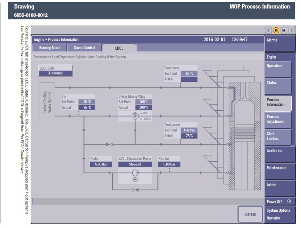
Currently, as shown in Figure 6, the 3-way valve is at position 2A to 1AB, so the liner jacket water is just circulating inside itself. At the same time, the LDCL circulation pump is off, so there is no liner water flow. This causes the Liner Jacket Cooling Differential Pressure Low Alarm.
The engine is stopped now, and the CWCU command signal is 20 mA. At 20 mA, the valve position should be 3B to 1AB to allow liner jacket water flow.
When I carefully checked the IP converter manual, I saw the command signal setting had options called “rising” and “falling.” It was originally set to “rising,” but I changed it to “falling.” I also changed the feedback signal setting from “rising” to “falling.”
This setting chooses whether the valve closes at 4 mA or at 20 mA. PID controllers and IP converters often have these kinds of settings. After changing the settings, everything started working well.
When starting the ship again, I found the ME jacket cooler temperature setpoint is not changing according to the ME load as it should. Actually, the CWCU sends the jacket cooler outlet temperature setpoint to the ME jacket cooler temperature controller based on the ME load.
Checking the wiring, everything looks normal. Looking closely at the temperature controller’s PCB, I found two DIP switches. One switch chooses between pressure control or temperature control. The other switch chooses between external setpoint or internal setpoint.
The controller was set to use the internal setpoint. After switching it to external setpoint, the setpoint changed according to the CWCU commands as it should.


I noticed that the jacket cooler outlet temperature value (process value) on the jacket cooler temperature controller is about 10°C different from the main engine jacket inlet temperature. Actually, even if they are not exactly the same, they should only differ by about 1°C or 2°C.
I also saw on the AMS monitor that the jacket cooler outlet temperature differs by about 10°C.

The PT100 sensor for the jacket cooler outlet temperature that sends data to the AMS and the PT100 sensor that sends data to the temperature controller come from the same place. They use one tube with two PT100 sensors inside. When I checked the resistance (ohm) values, both sensors showed the same value. So, the sensors are not faulty.
Then I checked the temperature controller settings and found a setting called TC gain. The manual says if you increase the TC gain, the process value (temperature reading) will increase.
The TC gain was originally set at 1000, so I gradually increased it until the temperature reading matched the actual temperature.
After these adjustments, the LDCL system worked properly without errors. The liner jacket water temperature is now controlled well according to the ME load, and the cylinder cover jacket outlet temperature stays steady at 85°C.
Reference:
- Hyundai MAN B&W, Marine Diesel Engine 6G60ME-C9.5 Instruction Manual
- MAN B&W, Service Letter SL2019-671/JAP, MAN B&W
- Anish, 2019, Understanding Hot and Cold Corrosion in Marine Engine, Marine Technology, Marine Insights
Kyaw Soe Aung (1255HR, 16FEB2025, Kuwait)
(This blog post is intended solely for educational purposes and knowledge sharing. It is not designed for commercial publication or professional use. The information provided aims to offer a general introduction to ME Engine Control Systems for those unfamiliar with the topic.
Please be aware that this overview is based on specific ME engines encountered and reflects current technology as of the date of writing. Due to the evolving nature of technology, there may be gaps, discrepancies, or inaccuracies in the information presented.
For the most accurate and up-to-date information, further research and consultation with industry experts are recommended. Corrections, additional insights, and feedback from the community are welcome to enhance the accuracy and usefulness of this material.)

Leave a comment