Previously, I briefly explained how the K-Chief 600 AMS system handles digital and analog input/output modules onboard, based on my own experience. I also shared how these modules interface with systems like Engine AMS, Tank Gauging, and Valve Remote Control, and mentioned some real-life troubleshooting cases I’ve encountered.
Now, before diving deeper into how these systems are integrated, it’s important to understand the serial communication standards that form the foundation of their communication.
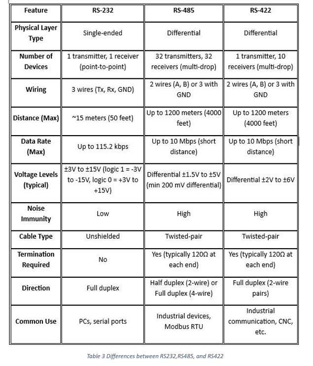
The most commonly used serial communication standards in marine systems include RS-232, RS-485, and RS-422, which are defined by TIA/EIA (Telecommunications Industry Association / Alliance). Simply put, these standards determine how one device communicates with another—specifying things like voltage levels, signal direction, and cable length limits.
So, what’s the difference between a communication standard and a communication protocol?
A standard like RS-232 or RS-485 defines the physical layer—how signals are transmitted, while a protocol like Modbus or TCP/IP defines how data is structured, interpreted, and exchanged between devices. It ensures that both devices understand each other’s message format, commands, and responses.
To make this clearer: consider Morse code as an analogy. The method of sending dots and dashes is the communication standard, while the code used to represent each character is the protocol. The same principle applies to RS communication and industrial protocols.
You can refer to Table 3 for a comparison of RS-232, RS-422, and RS-485 standards.
In Section (1), I mentioned that the AUMH (Analog Universal Module HART), DIOM (Digital Input Output Module), and TIM (Temperature Input Module) use the RS-485 communication method and operate based on the Modbus RTU protocol.
Although an ETO, as an end user, does not need to fully understand Modbus RTU to troubleshoot the system, they do need to know how the modules communicate with each other. Understanding the overall system structure and function is important so that the ETO can accurately scope the issue and report the problem precisely.
This knowledge helps in identifying whether the fault lies in cable connections, voltage levels, or elsewhere, allowing for clearer communication when raising a service request.
The AUMH, DIOM, and TIM modules use the Modbus RTU protocol, while the CPM module uses the Modbus TCP/IP protocol to communicate with the DGU SIO module. I have explained these communication methods in detail in Section 1 of this post.
Now, I would like to briefly explain the cargo alarm monitoring system of the K-Chief 600. The Cargo Monitoring System is connected to other systems such as the Tank Gauging System, Inert Gas (IG) System, Ballast Water Treatment System, and Valve Remote Control System.
On this ship, the Ballast Water Treatment System and the Tank Gauging System each have their own standalone Alarm Monitoring System (AMS). Meanwhile, the BWTS and Valve Remote Control System are integrated into the ACONIS AMS system located in the Engine Room.
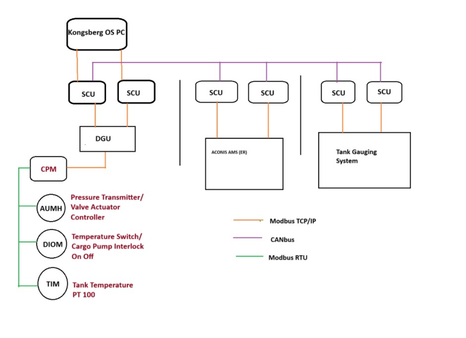
Each AMS and control system is connected to the DGU module and Analog/Digital Input modules through a Segment Controller Unit (SCU). The system uses the Modbus TCP/IP protocol over Ethernet cables for communication.
Currently, the system includes six Segment Controller Units: two for the Tank Gauging System, two for the Engine Room AMS, and two for sensors and switch interfaces on the deck. All SCU modules communicate with sensors and switch interfaces via CAN bus, and then connect over Ethernet to the Kongsberg OS computer.
Alarms generated by the system are displayed on the computer, while valves in the Engine Room can be operated remotely based on system status. The SCU and DGU units are all configured by the manufacturer, and generally do not allow configuration changes by the user. Even swapping Ethernet ports or cables does not enable configuration changes onboard.
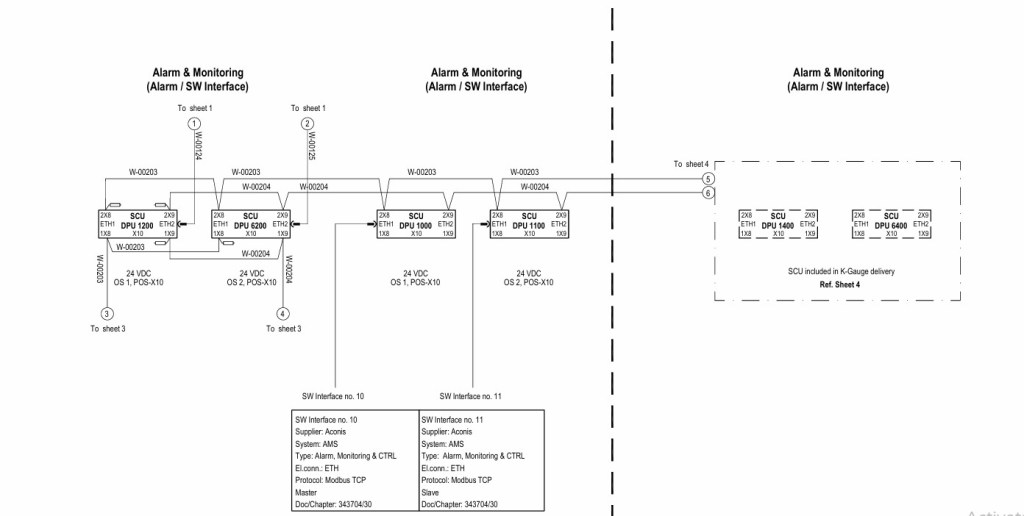
Figure 10 in the instruction manual shows the SCU wiring diagram in detail. Figure 11 illustrates the overall system architecture, which is similar to Figure 6 in the earlier section.
In the next part, I will share some common troubleshooting tips for this system based on my onboard experience.

Leave a comment