On normal vessels, we usually see Low Sea Chest and High Sea Chest arrangements.
However, on the ice-classed vessel I am currently working on, the configuration is different.
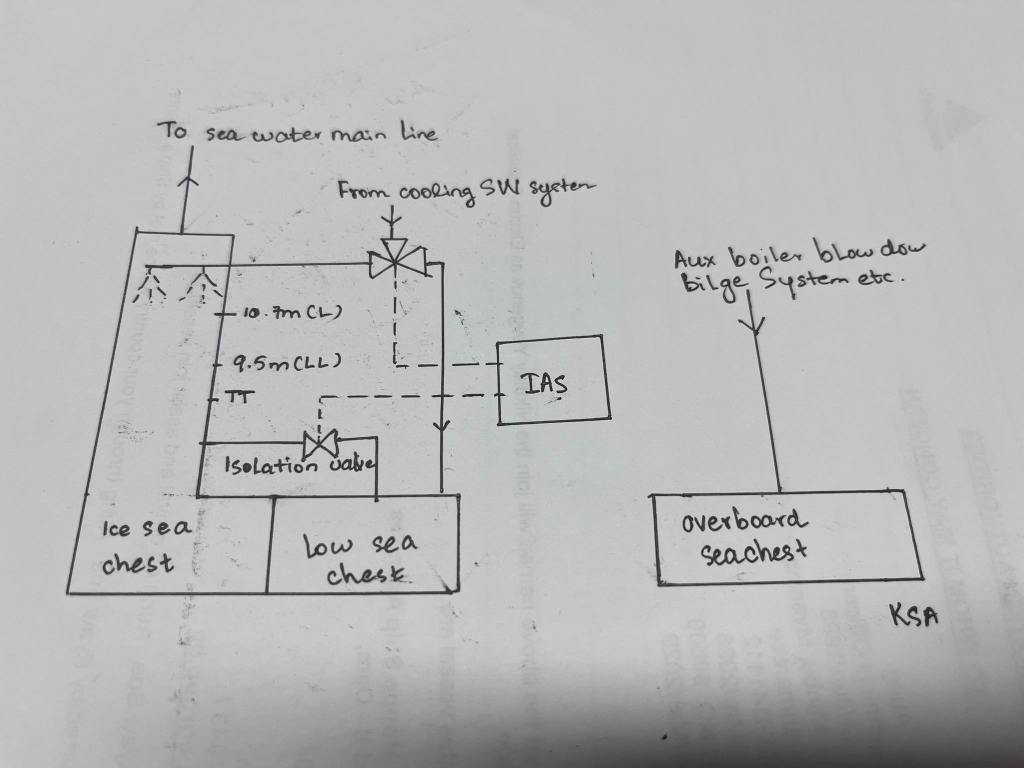
Instead of a high sea chest, the system is arranged with a Low Sea Chest and an Ice Sea Chest.
This post explains how seawater cooling is managed safely in icy conditions.
General Sea Water Arrangement
Sea water pumps take suction from the sea water main lines.
In this vessel, the sea water main lines are not directly connected to the Low Sea Chest.
They are connected directly to the Ice Sea Chest only.
The Low Sea Chest is not used for seawater suction.
Instead, it is used mainly to discharge return water from the engine room main cooling system.
Return Cooling Water Control
Cooling water returning from the main cooling system can be directed to:
- The Low Sea Chest, or
- The Ice Sea Chest
This selection is controlled by a 3-way control valve.
In addition, there is an Isolation Valve between the Low Sea Chest and the Ice Sea Chest.
This valve is controlled by the IAS (Integrated Automation System).
The overall control logic is based on:
- Water level in the Ice Sea Chest
- Sea water temperature
The purpose is to ensure stable sea water suction and prevent ice blockage.
Normal Temperature Operation
If:
- Ice Sea Chest water level is above 10.7 m from baseline, and
- Sea water temperature is above 10°C
Then:
- Return cooling water is directed by the 3-way valve to the Low Sea Chest
- The water is discharged overboard normally
Low Temperature (Ice Condition) Operation
When sea water temperature drops below 10°C:
- Return cooling water is directed to the Ice Sea Chest
- The water is sprayed from the top of the Ice Sea Chest
This helps:
- Maintain water temperature inside the Ice Sea Chest
- Prevent ice formation
- Improve suction conditions for sea water pumps
Ice Sea Chest Level Protection Logic
If Ice Sea Chest water level:
- Drops below 10.7 m → IAS generates a Low Level Alarm
- Drops below 9.5 m → IAS generates a Low-Low Level Alarm
At Low-Low Level:
- IAS automatically opens the isolation valve
- Sea water from the Low Sea Chest flows into the Ice Sea Chest
- This helps restore water level and maintain suction
Air Vents and Heating Arrangement
To ensure that sea chests always remain full of water:
- Air vent pipes are installed on all sea chests
To prevent freezing:
- Air vent lines are fitted with heat tracing systems
- Vent pipelines are polyethylene coated to prevent ice buildup along the line
Sea Chest Heating and Piping
All sea chests are equipped with:
- Steam heating coils / steam heating lines
These heating lines:
- Prevent ice formation inside the sea chest
- Help maintain seawater temperature during extreme cold conditions
Although return cooling water is discharged through the Low Sea Chest:
- Bilge Water Separator discharge
- Clean drain pump discharge
- Boiler blowdown
- Bilge discharge
are routed through separate overboard sea chest.
This prevents:
- Chemicals
- Oil residues
- Solid particles
from entering the sea water cooling system.
Extreme Ice Conditions – Emergency Operation
If ice becomes so thick that:
- Seawater cannot be suctioned from either the Low Sea Chest or the Ice Sea Chest
Then:
- Pre-stored seawater in two Engine Room Ballast Tanks is used
In this condition:
- Only essential cooling systems are kept in operation
- Non-essential consumers must be shut down to conserve seawater
This explanation is based on:
- Onboard observations
- System manuals
The diagram used was personally drawn based on the IAS HMI view, simplified for clarity.
Similar systems may exist on other ice-classed vessels.
This is the first time I have personally encountered this configuration.
The purpose of this post is not to describe every pipe and heating detail,
but to explain how sea chest operation is managed in ice-covered seas.

Leave a comment