May 24, 2023 Rotterdam
The ship is experiencing a High Alarm for Main Engine Tachometer Discrepancy. According to the Chief Engineer (CE), this alarm has been present since the ship was handed over from another management. A High Tachometer Discrepancy indicates that one of the tachometers is malfunctioning. After consulting with my fellow ETOs and checking thoroughly, this understanding is confirmed. The manual also states that an alarm will occur if there is a discrepancy between the two tachometers.
The Main Engine is a CME MAN B&W 8L27/38, a 4-stroke engine. It drives the gearbox and the propeller. From my previous experience with 4-stroke Main Engines with gearbox types, the Main Engine would run at a fixed RPM, and the propeller speed would be controlled by adjusting the gearbox. However, on this ship, it is different; the RPM of the Main Engine fluctuates according to the gearbox adjustments, similar to an automatic gear-driven car.
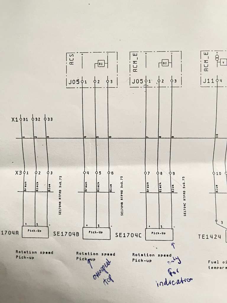
Knowing what the alarm is, I thought it would be simple to locate and replace the faulty tachometer. The challenge is that under the “Don’t touch it if it is working” policy, we are not allowed to make adjustments freely. It seems that the previous management, while attempting to fix the issue, swapped the two PNP pickup sensors used for the governor control, which led to the problem. Therefore, it appears that the current CE instructed not to touch the RPM sensors during the handover. This was also noted in the drawings they provided.
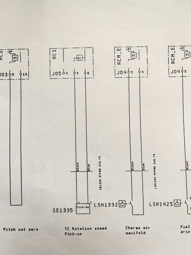
The Main Engine is equipped with five tachometers. Two of them are for the Governor Control Unit, and the remaining three are connected to the Engine Control System. According to the alarm list in the manual, the current alarm is from the Engine Control System.
First, to determine whether the Main Engine RPM aligns with the speed order and to verify the accuracy of the Main Engine RPM, I wanted to check using a portable tachometer. However, we do not have a portable tachometer available. Attempts to read the RPM through the Revolution Counter also failed as it is not working.
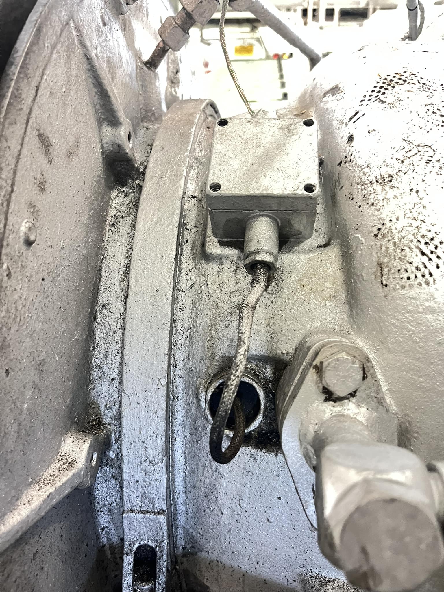
So, the first step is to fix the easily repairable Revolution Counter. It has a PNP pickup sensor attached, which sends signals to the Frequency Driver in the ECR console. The Frequency Driver then provides a signal to the Revolution Counter to count. Upon inspecting the PNP pickup sensor, it was found that the sensor was damaged and broken due to it coming into contact with the metal plate attached for pickup sensing on the flywheel. The stand holding the sensor was found to be loose due to engine vibrations, causing the sensor to touch and damage the metal plate. The metal plate was also not perpendicular to the sensor position, so it needed to be adjusted slightly.
It seems that under the previous management, a Smart Ship System was used with a Main Engine Data Logger. However, this system has now been completely removed. The system’s sensor mounting location for logging Engine RPM was left vacant, and the pickup for the Revolution Counter was reinstalled there. After reinstalling the pickup and checking the Revolution Counter with the RPM during engine operation, it was observed that the readings were accurate.
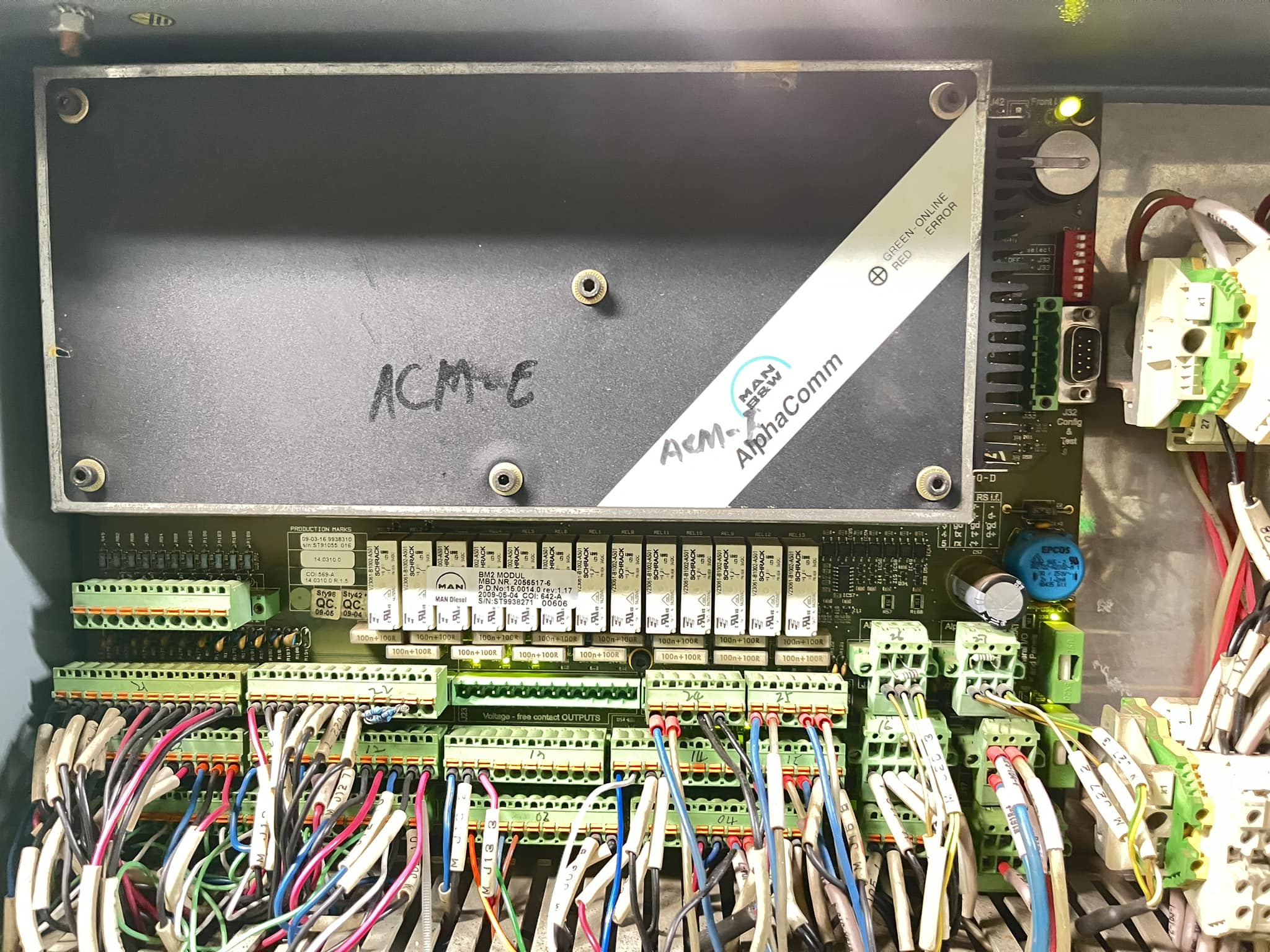
The Main Engine Control System is MAN B&W’s AlphaComm. It consists of two control units: AlphaComm Monitoring Engine (ACM-E) and AlphaComm Safety (ACS). Out of the three tachometers, two are connected to the ACM-E, and the remaining one is connected to the ACS. Of the two connected to the ACM-E, only one is currently in use, while the other is not connected to anything and seems to be kept as a spare. It appears that one of the remaining two tachometers is malfunctioning, which is causing the High Discrepancy alarm.
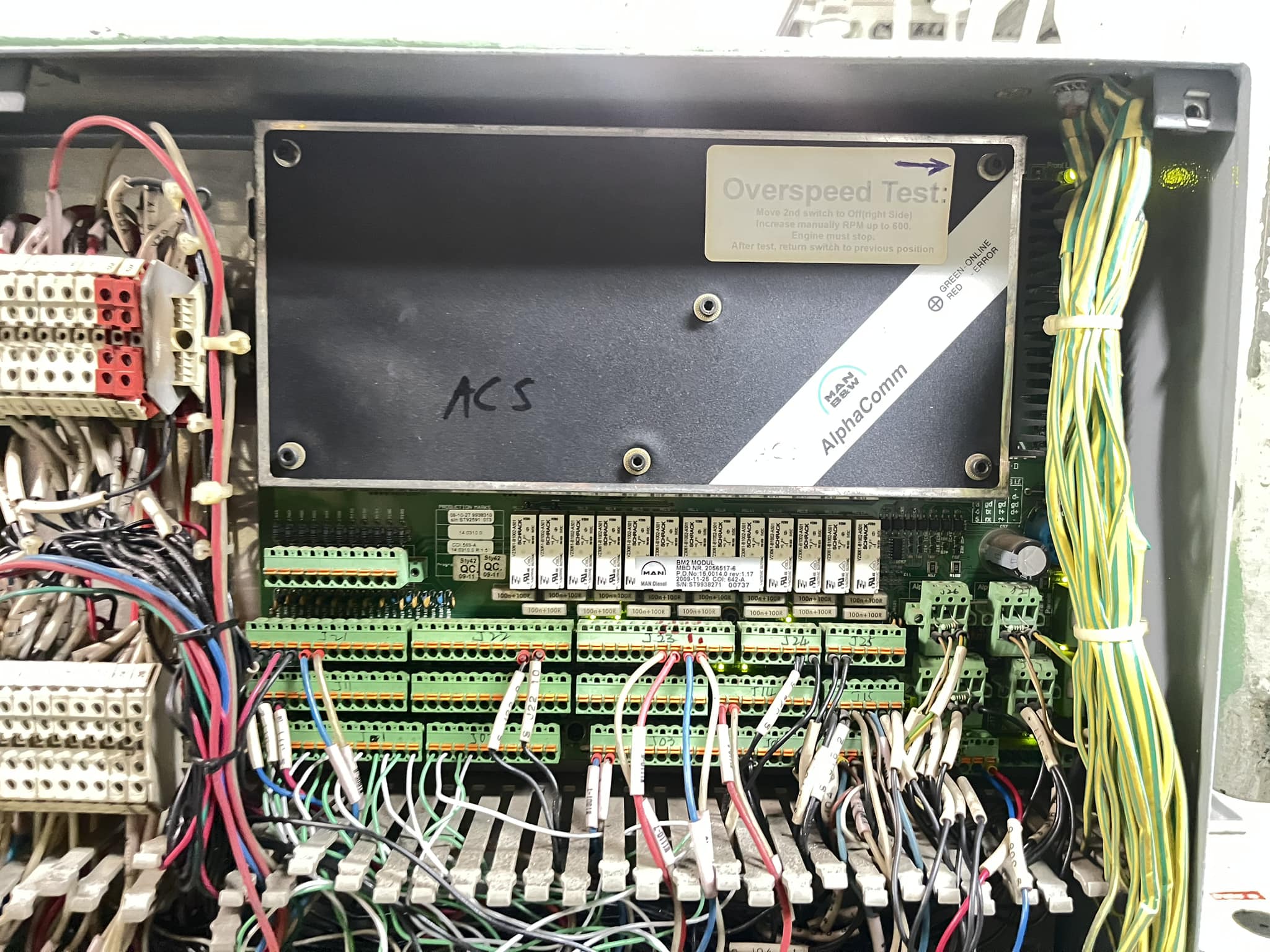
First, as a simple step, I decided to swap the spare tachometer that was left unused in the ACM-E with one of the working tachometers. Even after swapping each tachometer individually and testing both, the High Discrepancy alarm still persists. I also checked each meter individually while turning the engine with the turning gear, and all readings appeared normal.
I examined the cable terminals and checked the junction box where the cables lead to the Engine Control Unit, using spare cables to test each connection. All of this was done while the engine was stationary. In reality, testing while the engine is running would provide more accurate information, but the CE did not permit it. Although testing while running could yield better results, considering that I’ve just arrived on the ship and am not familiar with this type of vessel, and given that the company is new, I followed the instructions to test while stationary. I understand the concern about potential delays due to the fixed schedule between two ports.
Testing each component one by one like this has been going on for about a month. One positive aspect is that, since the ship is gear-driven, the engine can be operated without engaging the gear. Therefore, after mooring and providing the FWE (Final Water Examination), I consulted about keep running the engine for a moment, and I eventually received permission to do so.
The PNP pickup sensor uses three wires as shown in the diagram: Brown, Blue, and Black. The Brown wire provides a 24 VDC supply, the Blue wire is ground, and when the PNP sensor senses the metal (flywheel tooth), the Brown and Black wires make contact, resulting in 24 VDC appearing on the Black wire. By turning the gear and flywheel, it is possible to check if 24 VDC is present on the Black wire. Both tachometers show normal 24 VDC on-off behavior when tested with the turning gear. However, when the engine is running, the RPM is at least around 450, so the voltage signal changes rapidly, making it difficult to observe clearly.
Comparing the two tachometers from the ACM-E and ACS units, the tachometer connected to ACM-E shows a steady 10 VDC between Black and Blue (Ground), with only minor variations in mV. In contrast, the tachometer connected to the ACS shows only 3 VDC between Black and Blue (Ground). There is a significant difference between 10 VDC and 3 VDC compared to 24 VDC. Additionally, when measuring the supply voltage between Brown and Blue, the ACS tachometer only shows around 6 VDC.
When I removed the tachometer wires and checked the 24 VDC supply, it was still only 6 V. However, when the ship was stationary and I checked again, the 24 VDC supply was restored. This is why the issue was not found during the earlier tests when the ship was stationary. The tachometer is connected to the ACS module through J5, where it shares connections with the turbocharger RPM sensor. I also checked to ensure that the tachometer wires were not grounding out, and they were in good condition. When reconnecting the wires and measuring the supply voltage for the tachometer again, I noticed that the voltage consistently remained at 6 VDC.
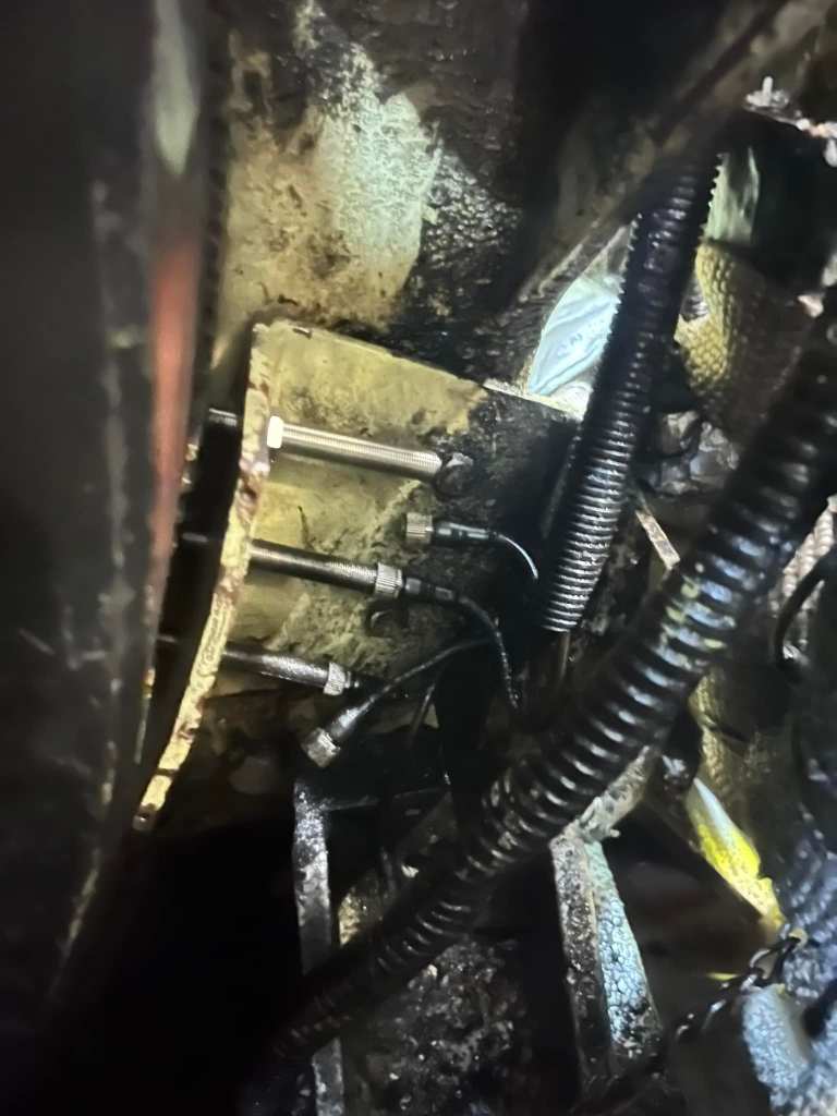
I reconnected the J5 terminal plug and checked each wire individually. When reconnecting the wires for the turbocharger RPM sensor, I noticed that the supply voltage for the engine tachometer dropped. Upon inspecting the turbocharger RPM sensor, I found that one of the two wires was intermittently grounding. It was not a constant ground but rather occurred intermittently.
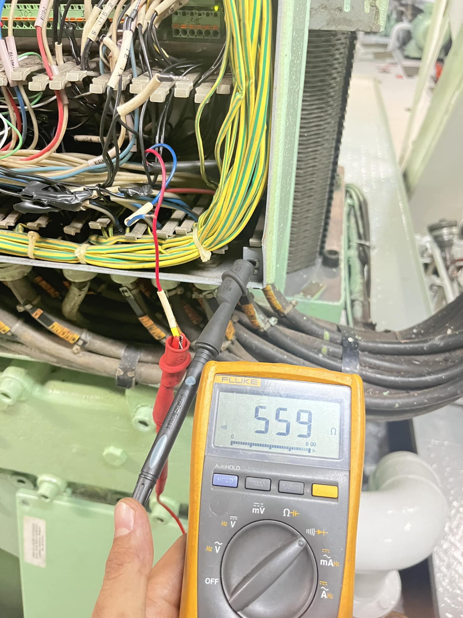
It’s quite unusual. The grounding issue is with the turbocharger RPM sensor, but the problem is affecting the engine tachometer. There is no issue with the turbocharger RPM indication itself; the voltage drop is occurring only on the tachometer side, which is causing the Tachometer Discrepancy High Alarm. I need to check if the wires leading to the turbocharger RPM sensor are grounding out. Finally, it was found that while all the wires were in good condition, the turbocharger RPM sensor side is experiencing grounding issues.
When I disconnected the turbocharger RPM sensor wire while the engine was running, the ME tachometer discrepancy high alarm disappeared.
Disconnecting the turbocharger RPM sensor would typically require removing the entire turbocharger, and if a new sensor is needed, there is no spare available, which would involve significant time and manpower. Therefore, I decided to disconnect and test the sensor.
Since the sensor cable was entangled within the turbocharger housing, I carefully removed as much of the cable as possible from outside, ensuring that the wires did not come into contact with anything else. After doing this, the grounding issue was resolved, and the tachometer discrepancy alarm no longer appeared.
Kyaw Soe Aung

Leave a reply to Jithin daniel Cancel reply